an old project (finished)


-
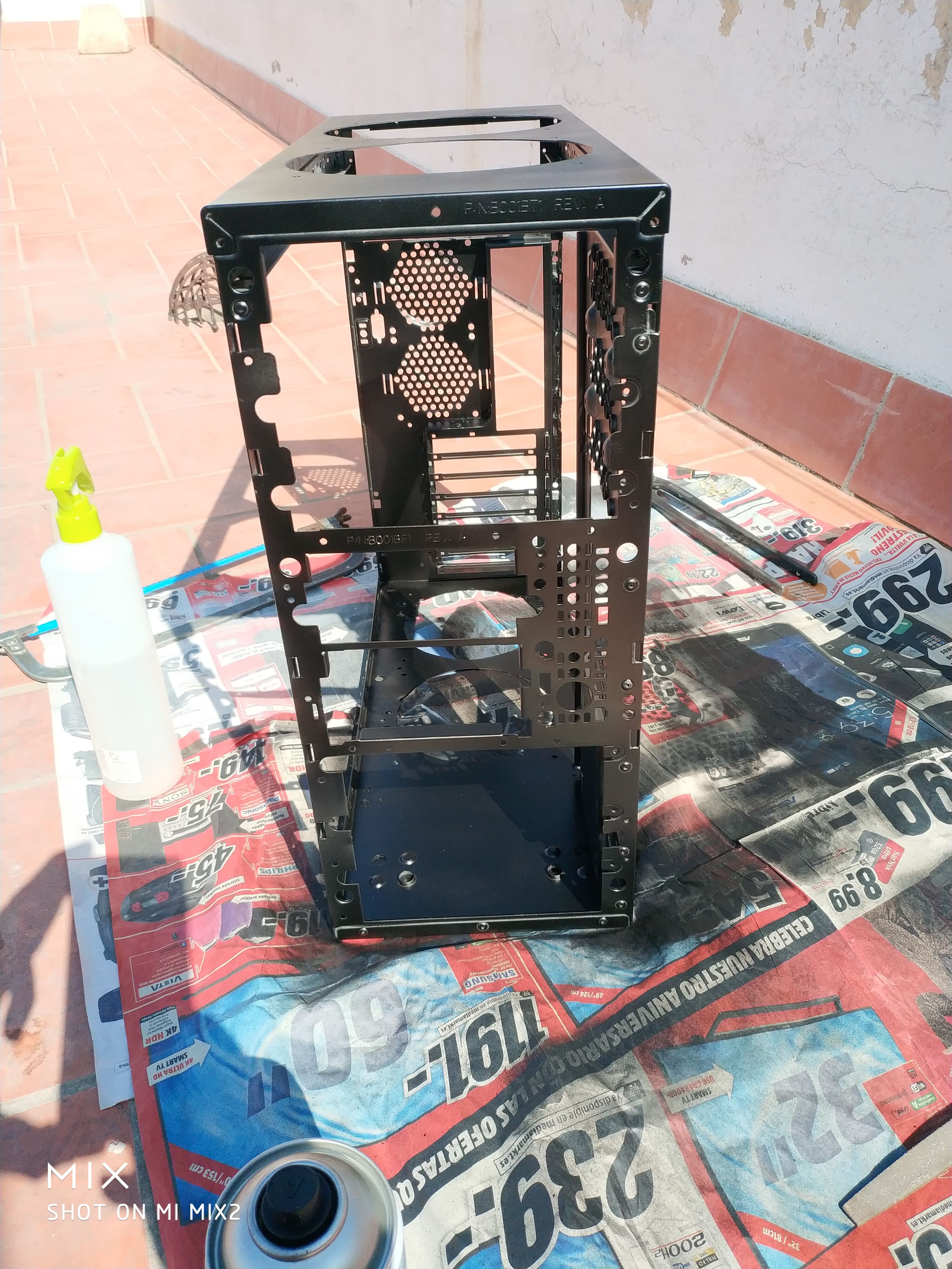
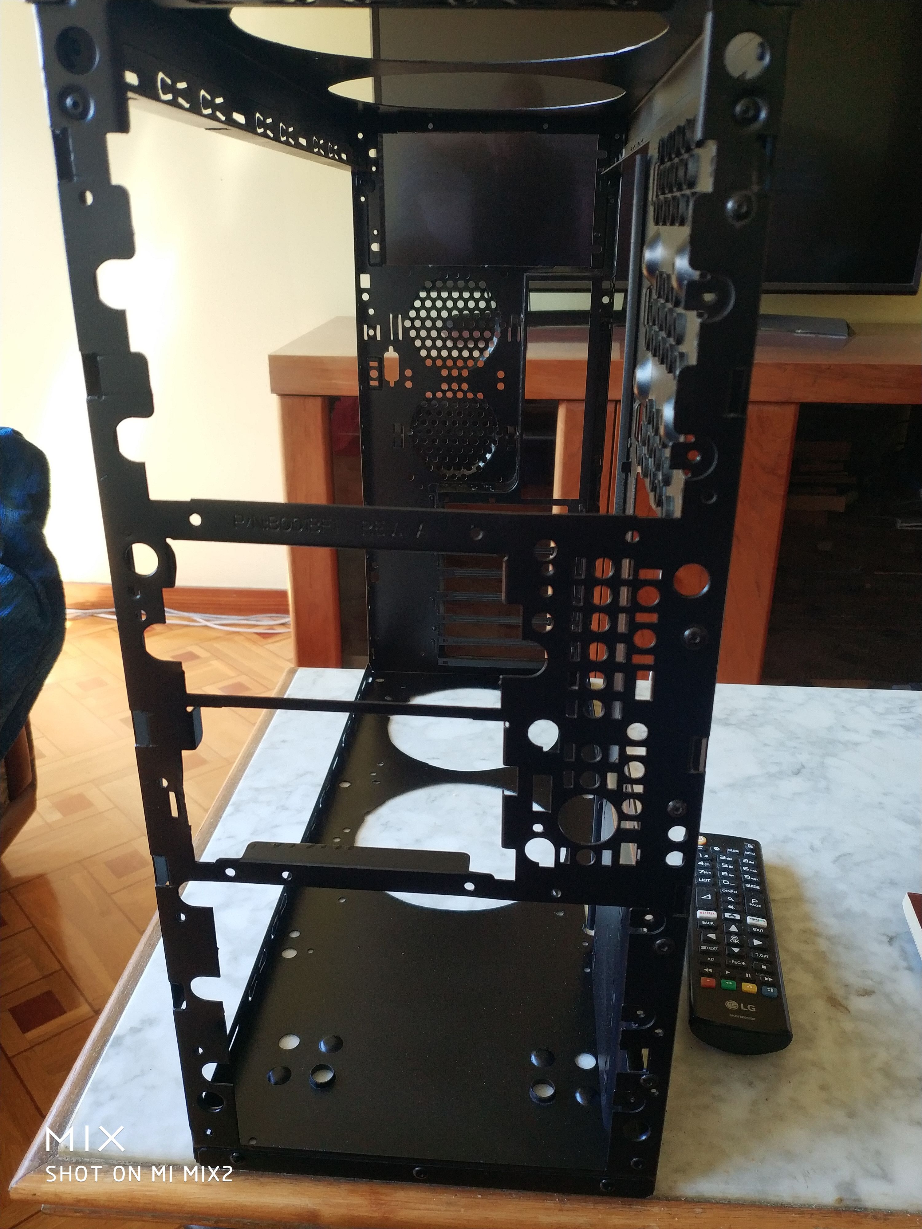
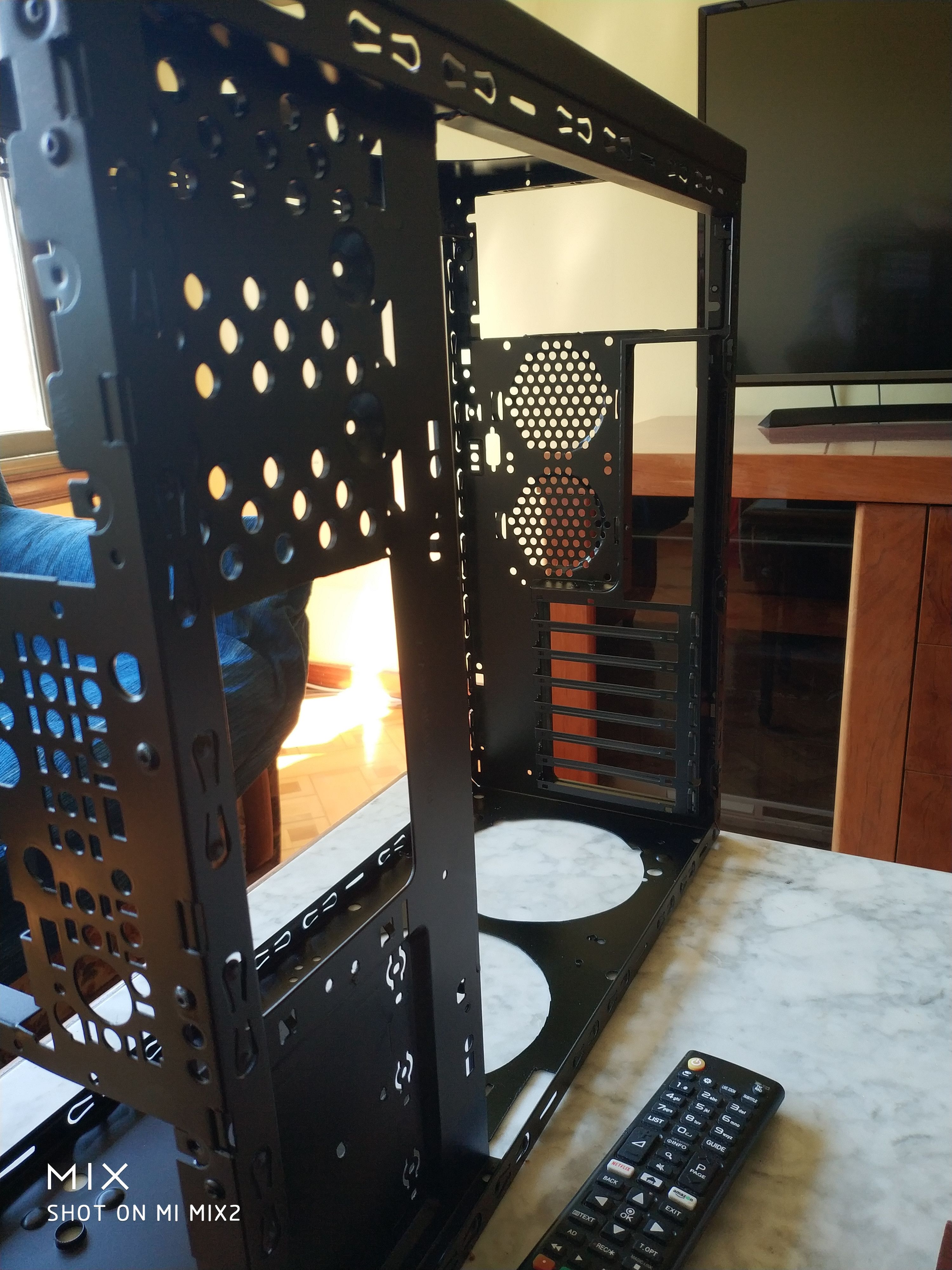
Este es un proyecto de modding de una torre de PC que se ha ido desarrollando a lo largo del tiempo. Aquí tienes un resumen de los pasos y las decisiones tomadas durante el proceso:
1. Diseño Inicial y Problemas Iniciales:
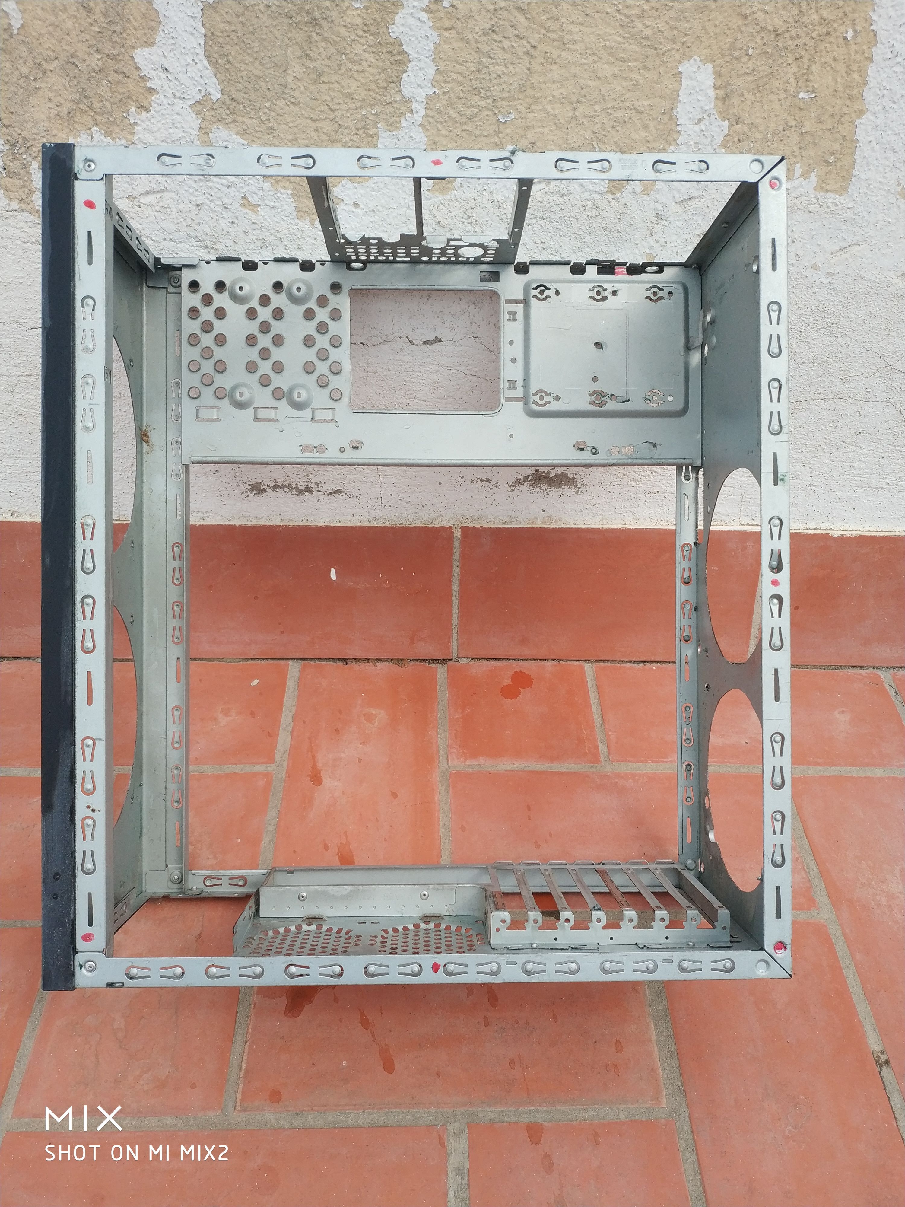
El usuario comenzó con un diseño que incluía la modificación de una torre existente para mejorar su ventilación y estética. Sin embargo, se encontró con varios desafíos, como la falta de herramientas adecuadas y la necesidad de improvisar soluciones.
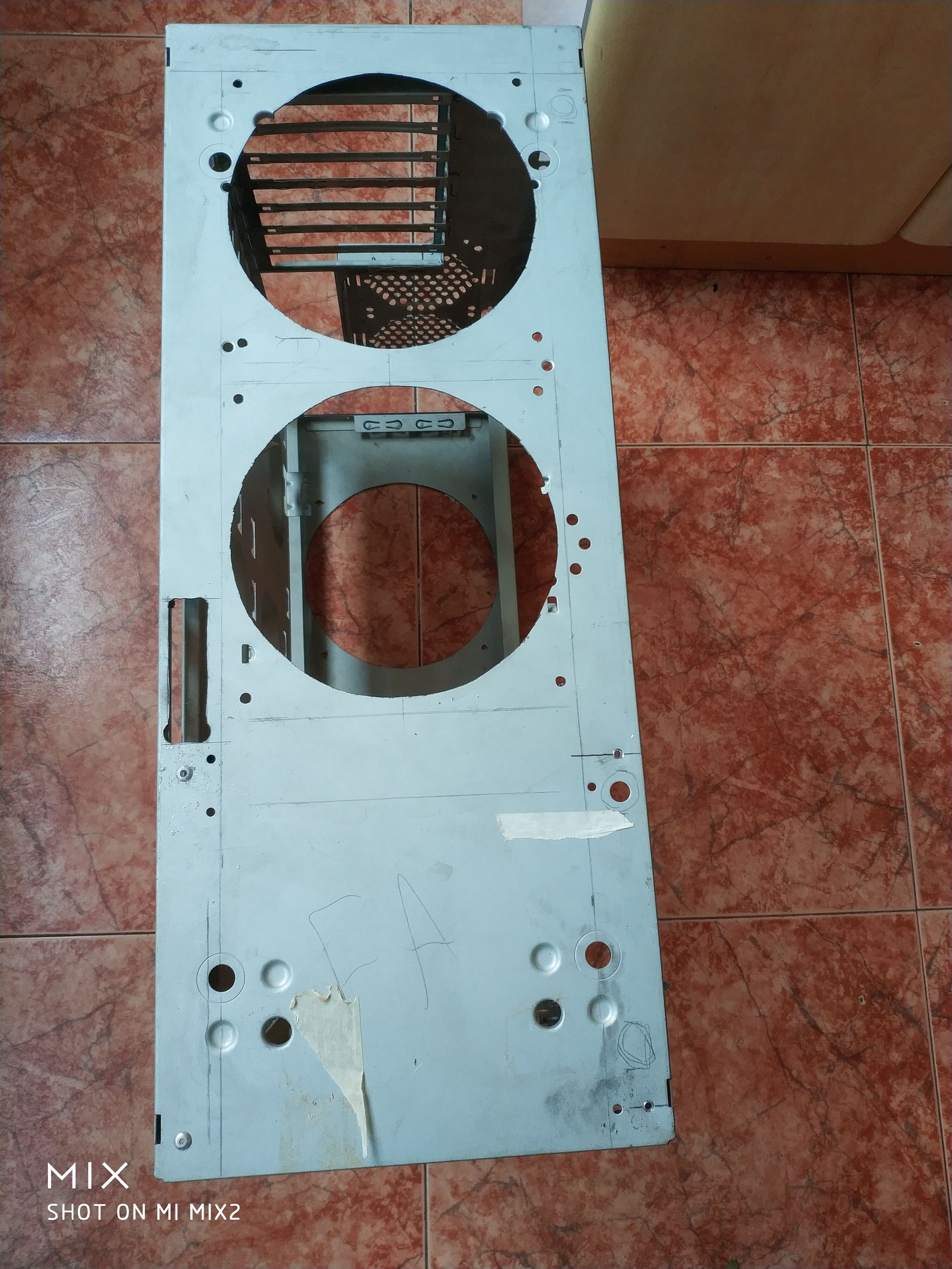
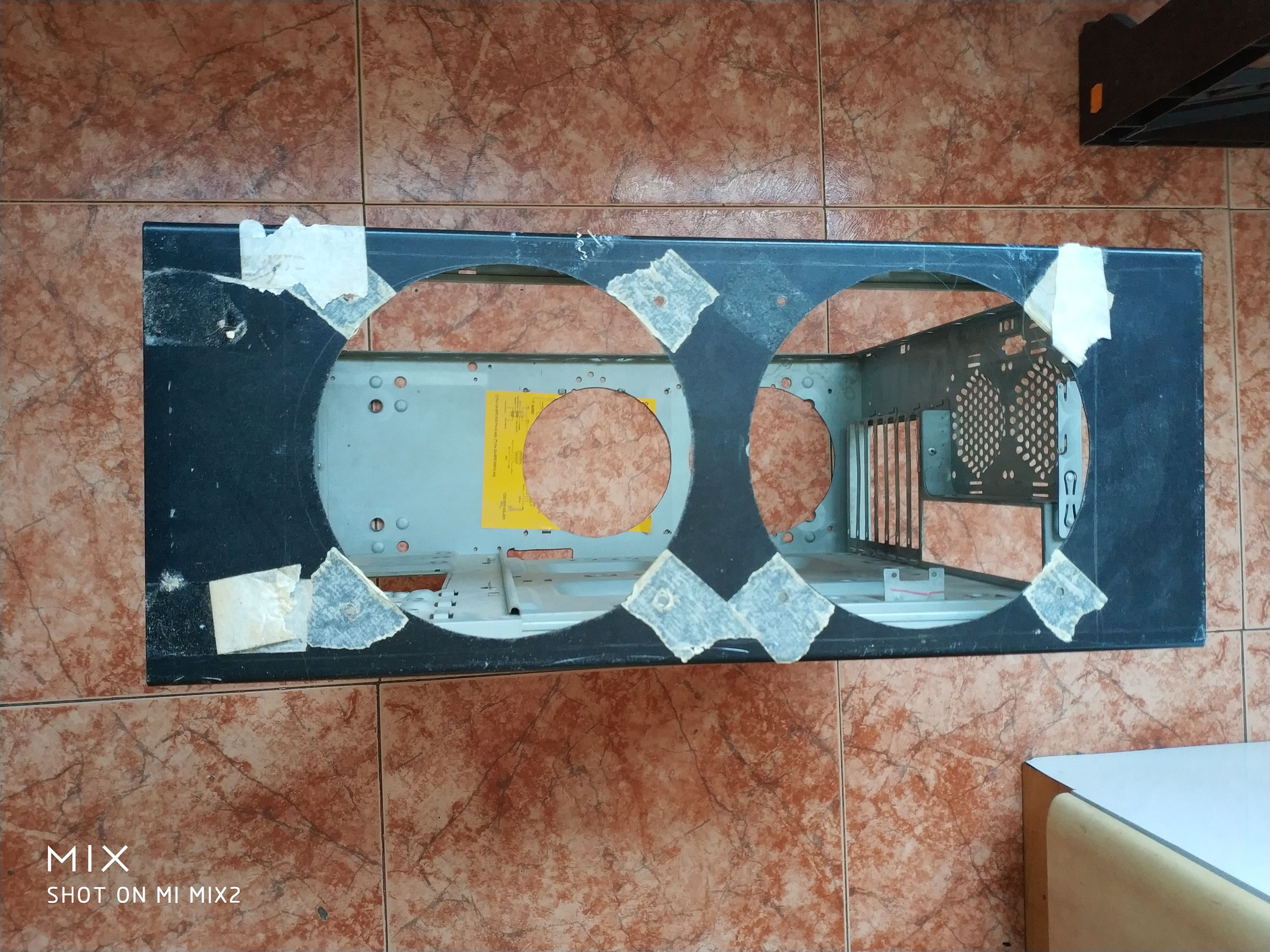
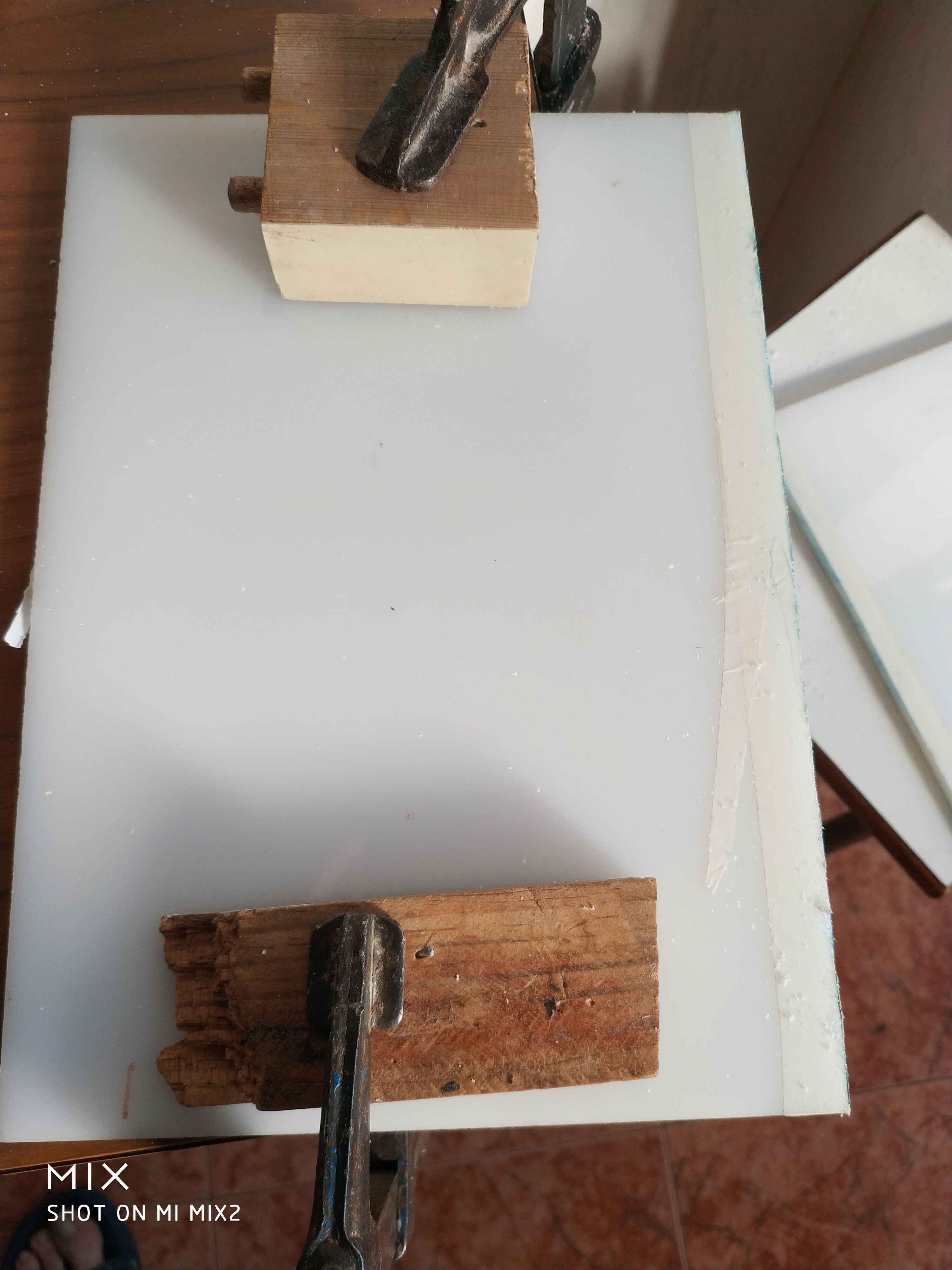
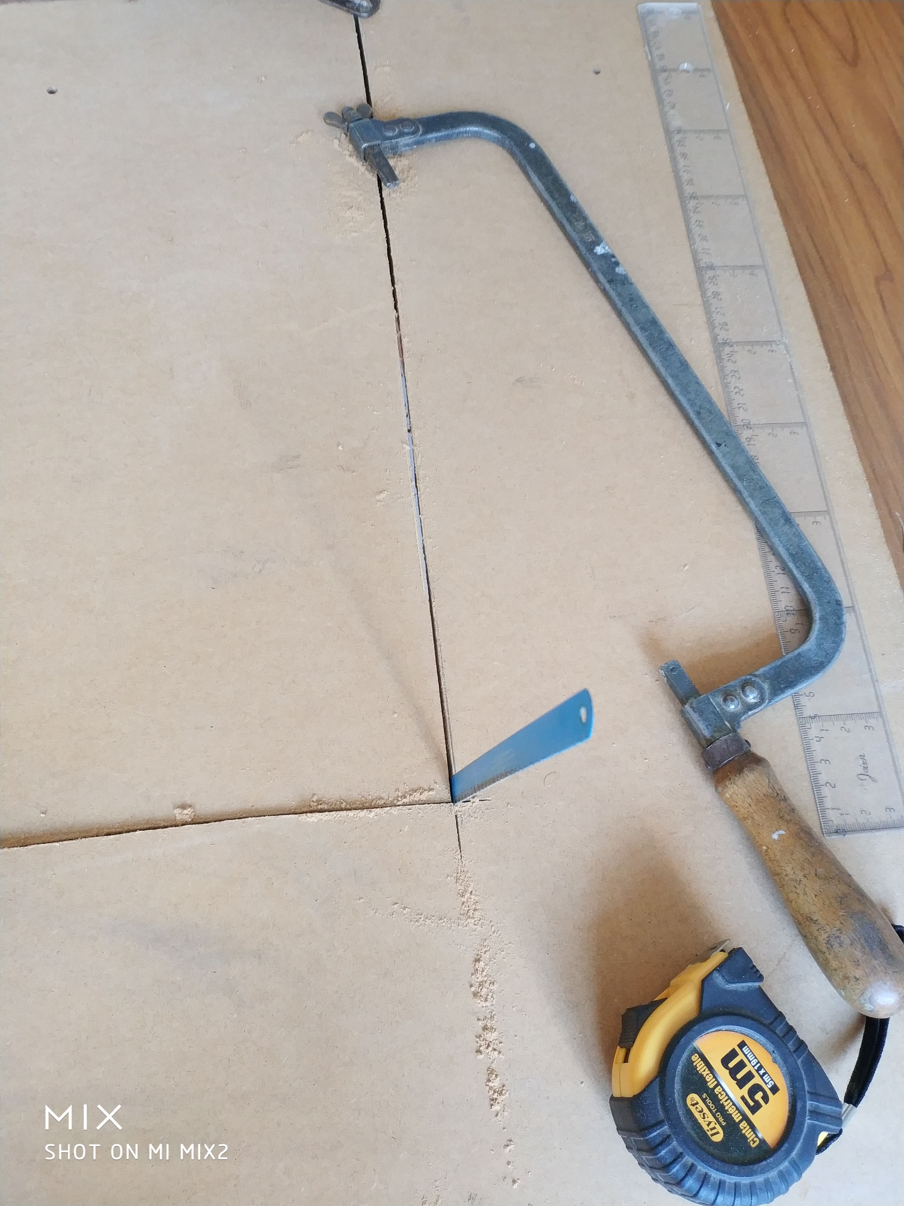
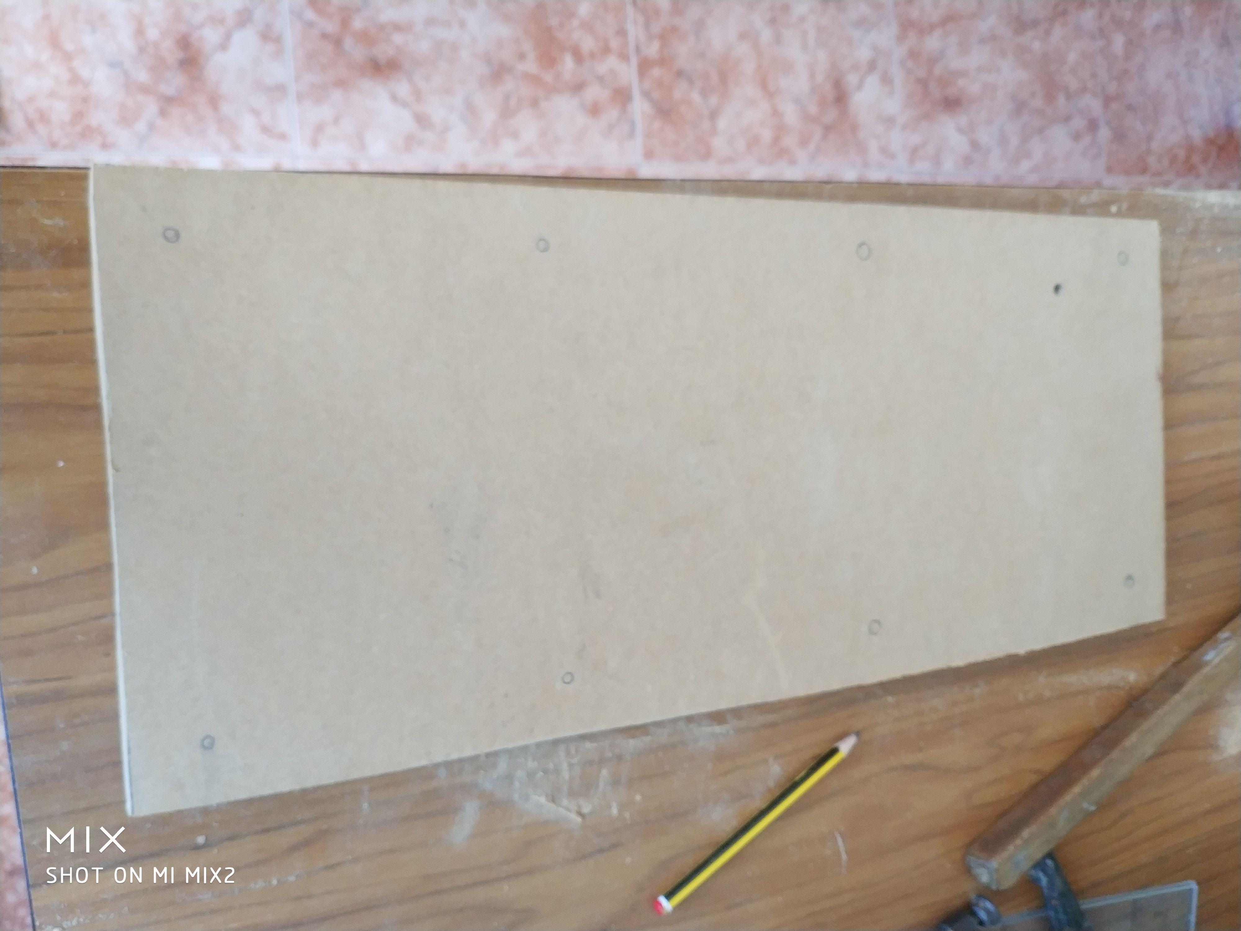
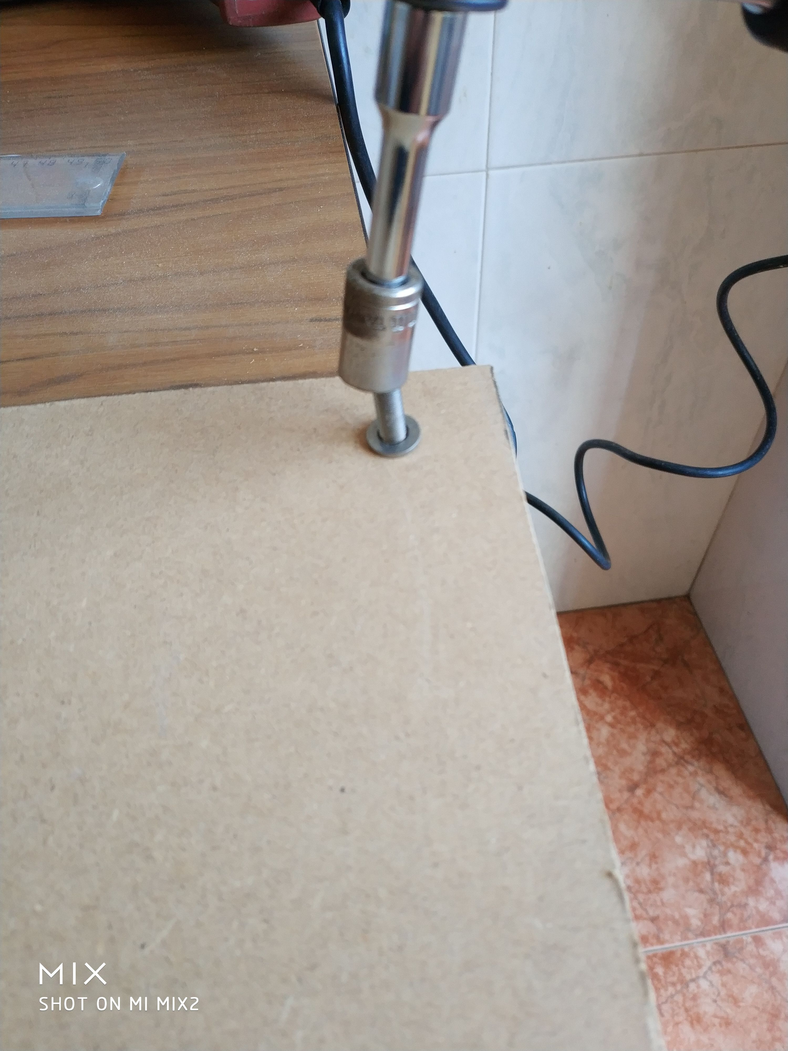
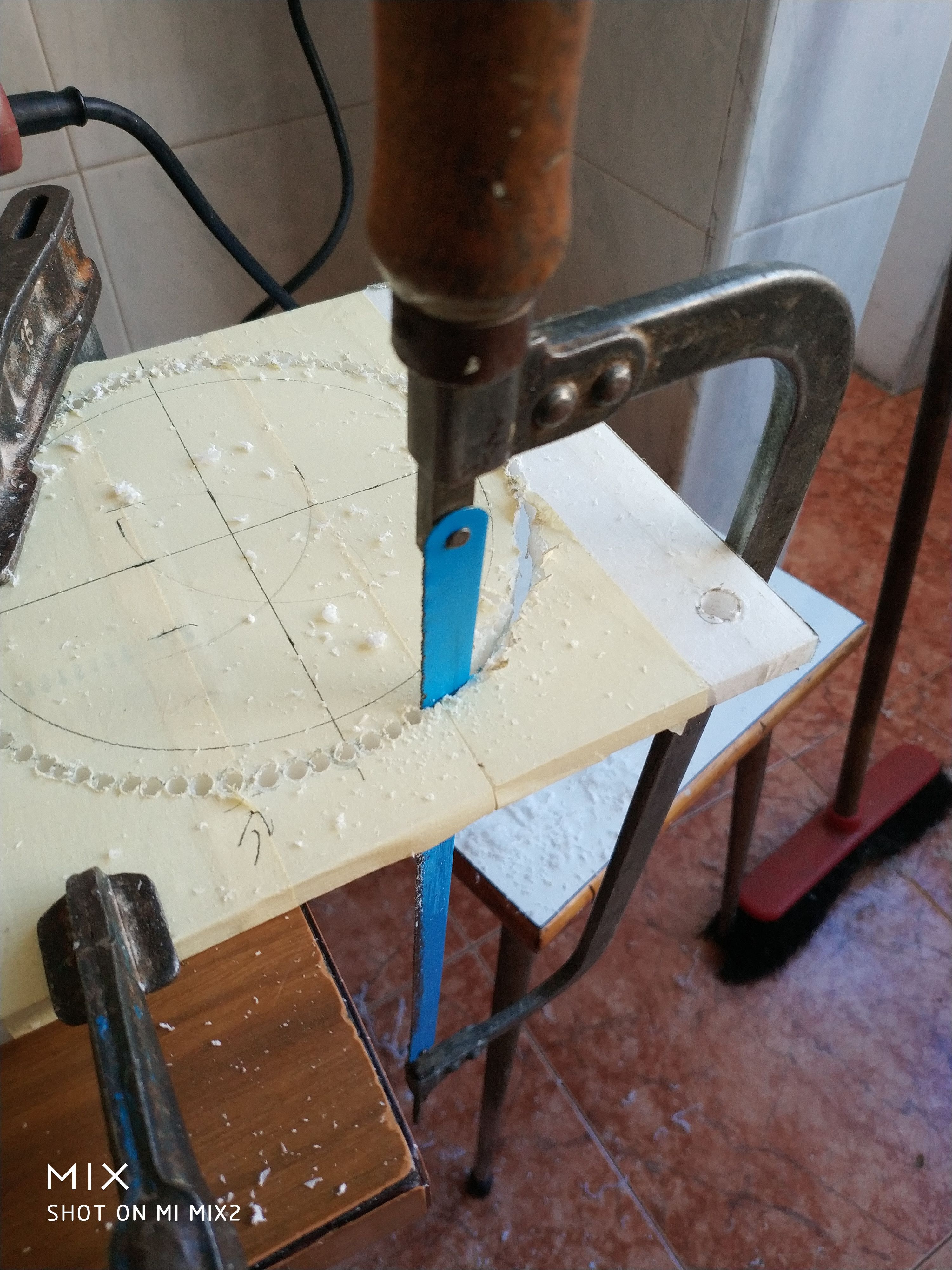
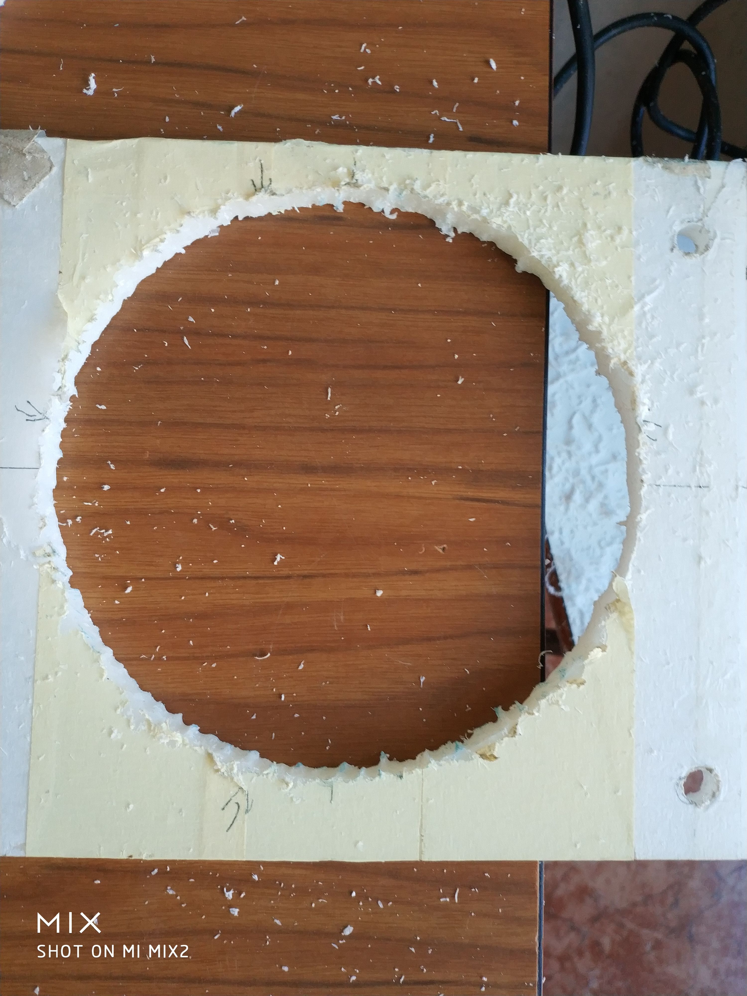
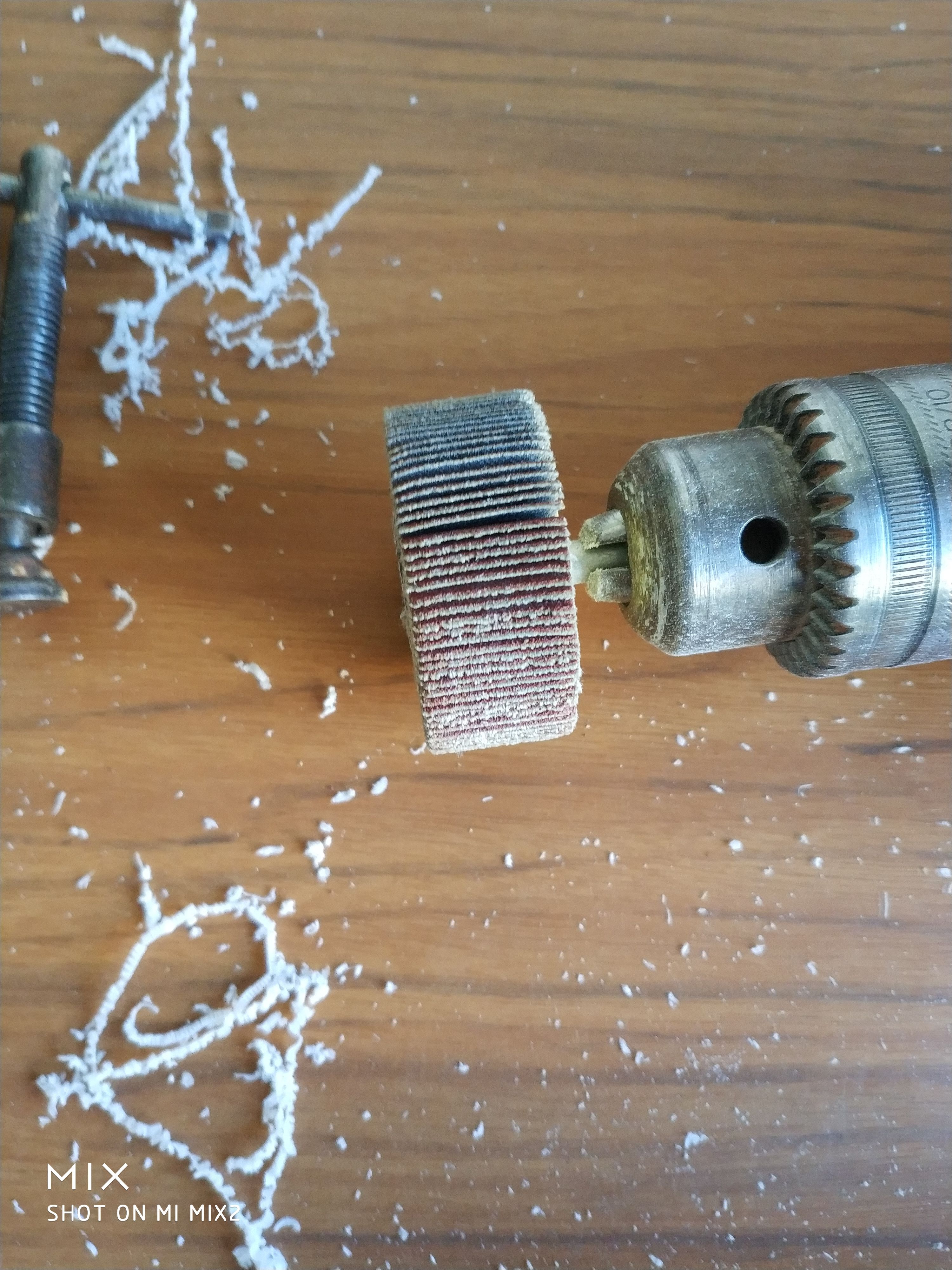
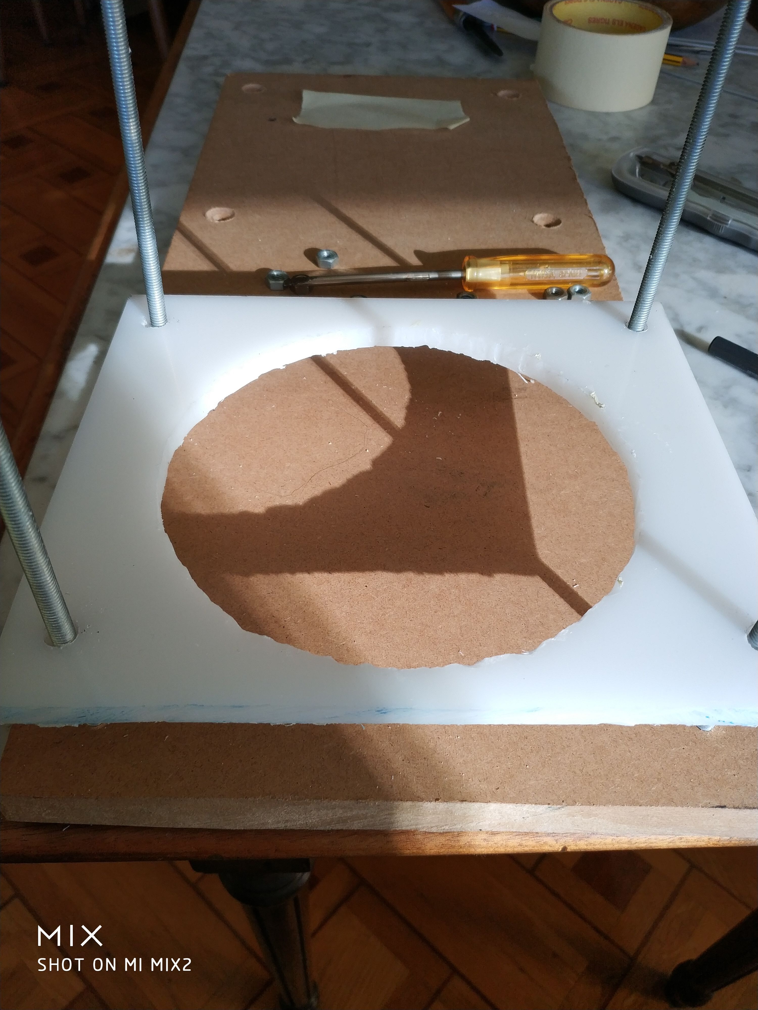
2. Mecanizado y Fabricación:
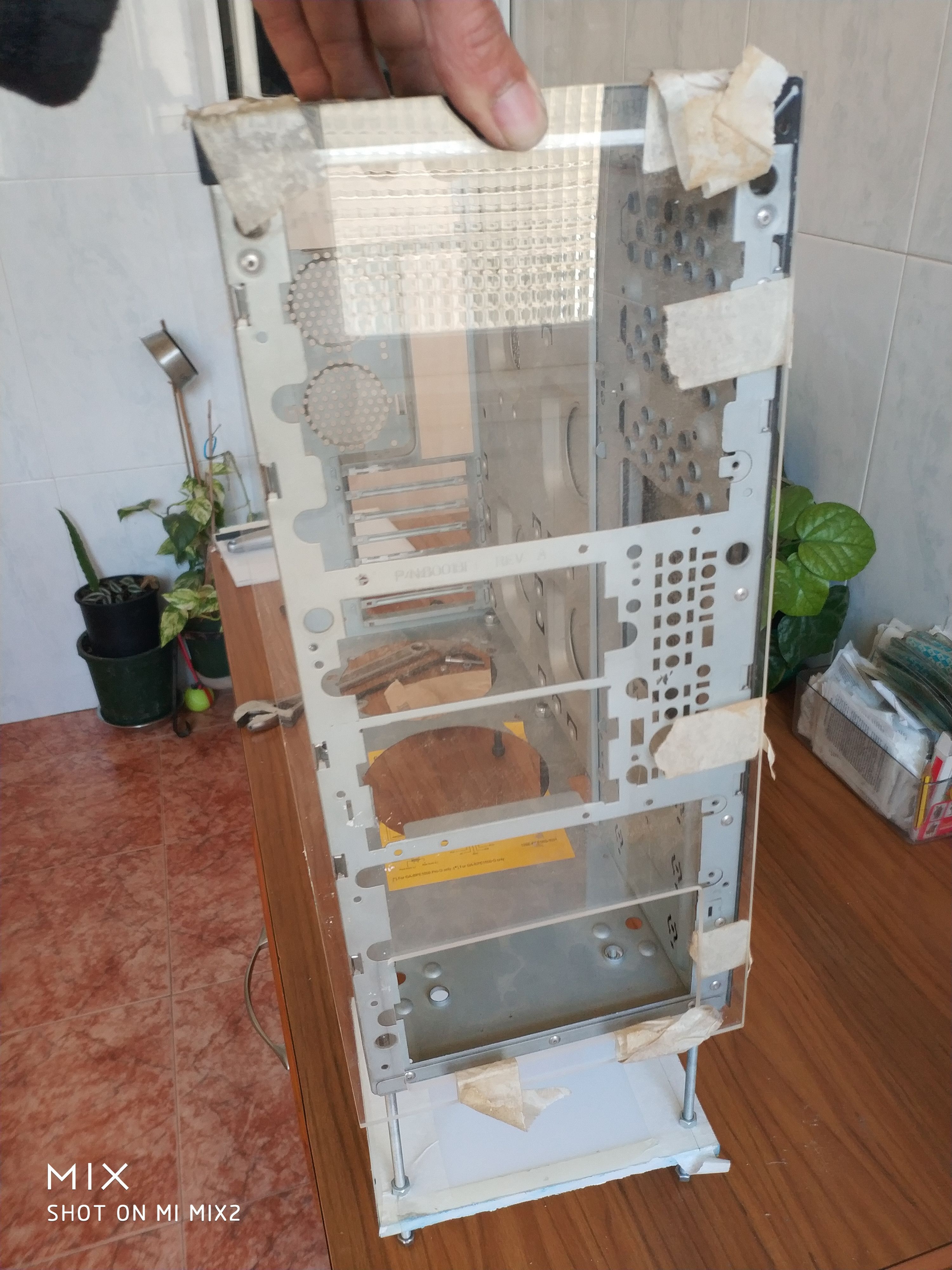
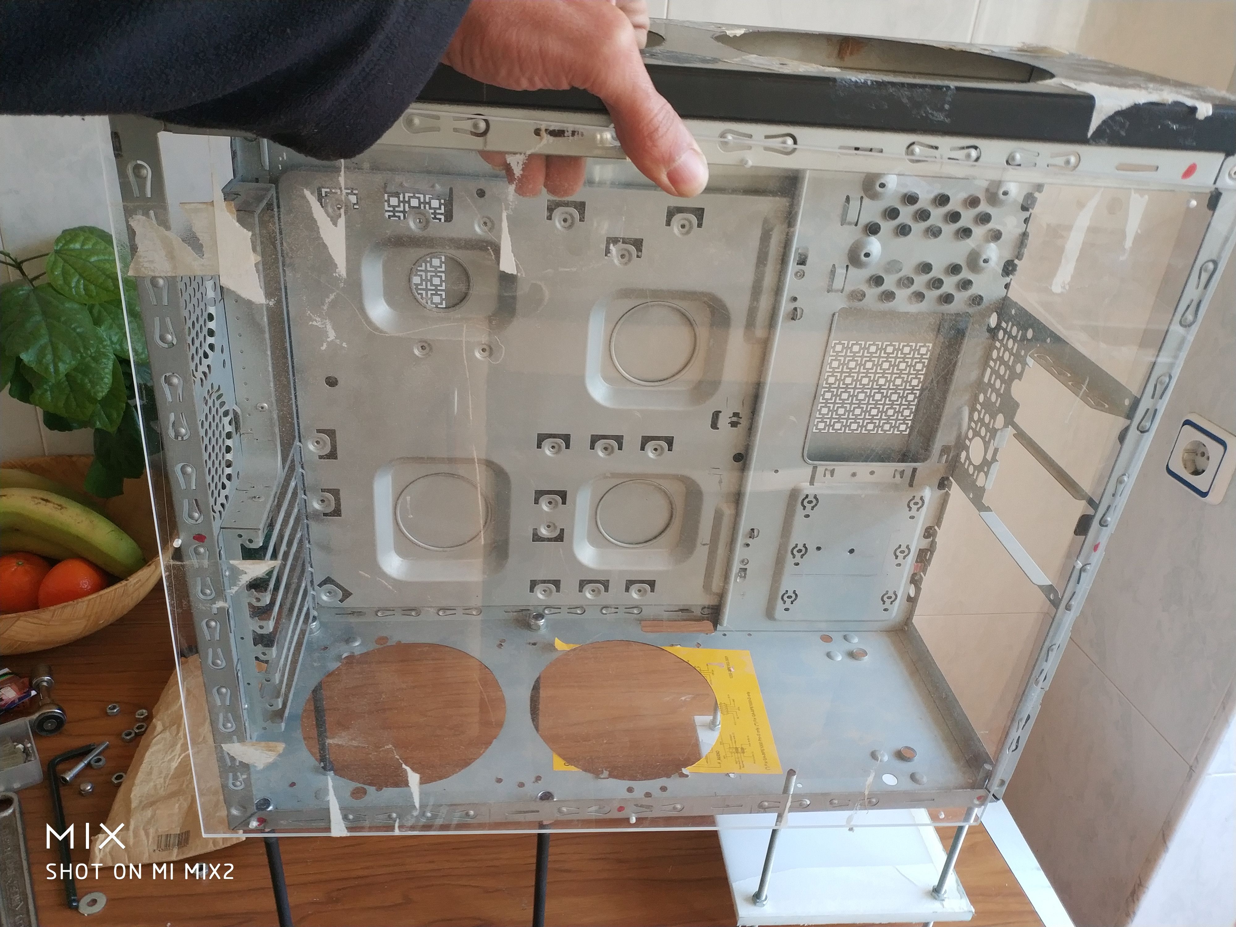
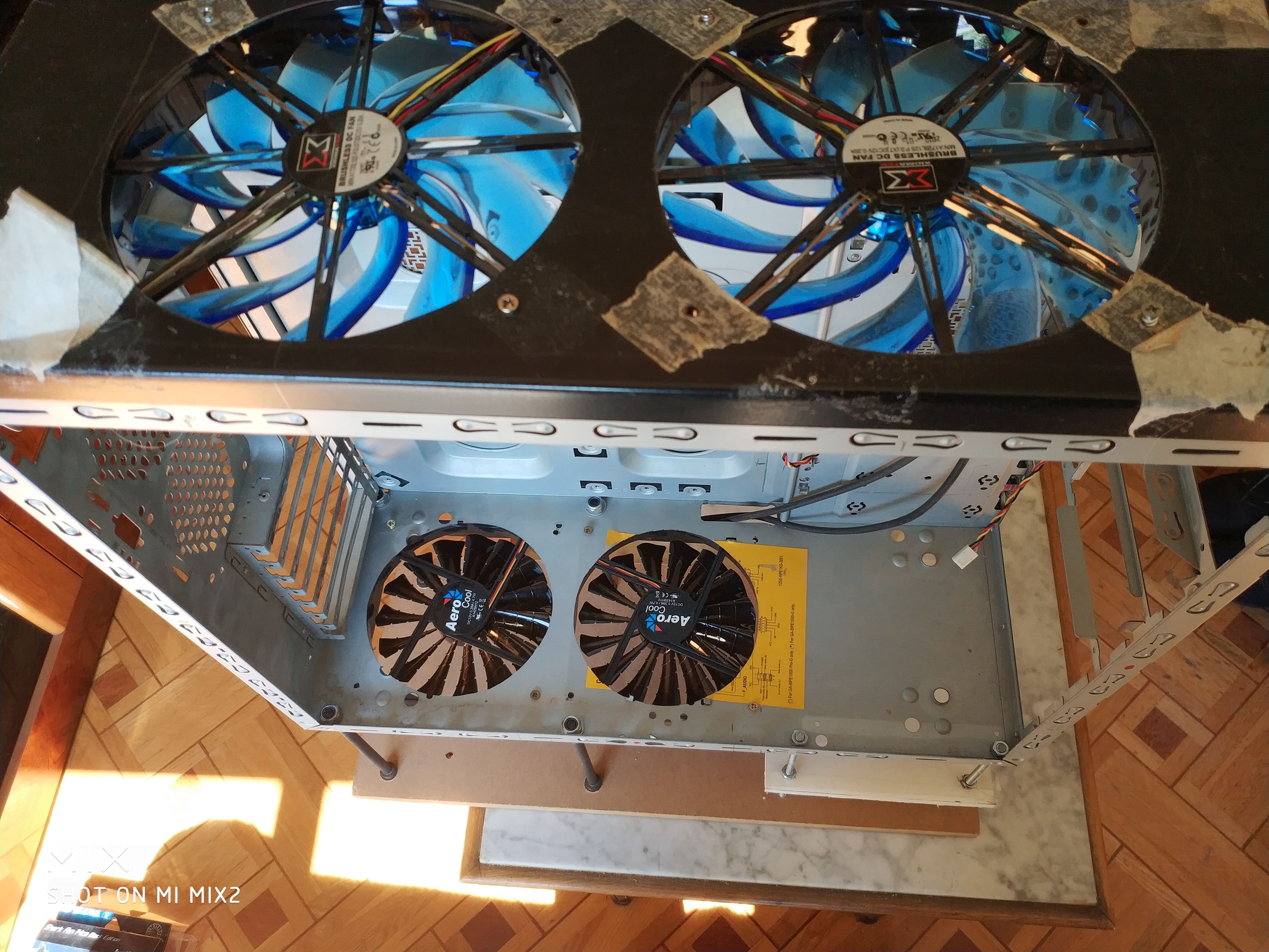
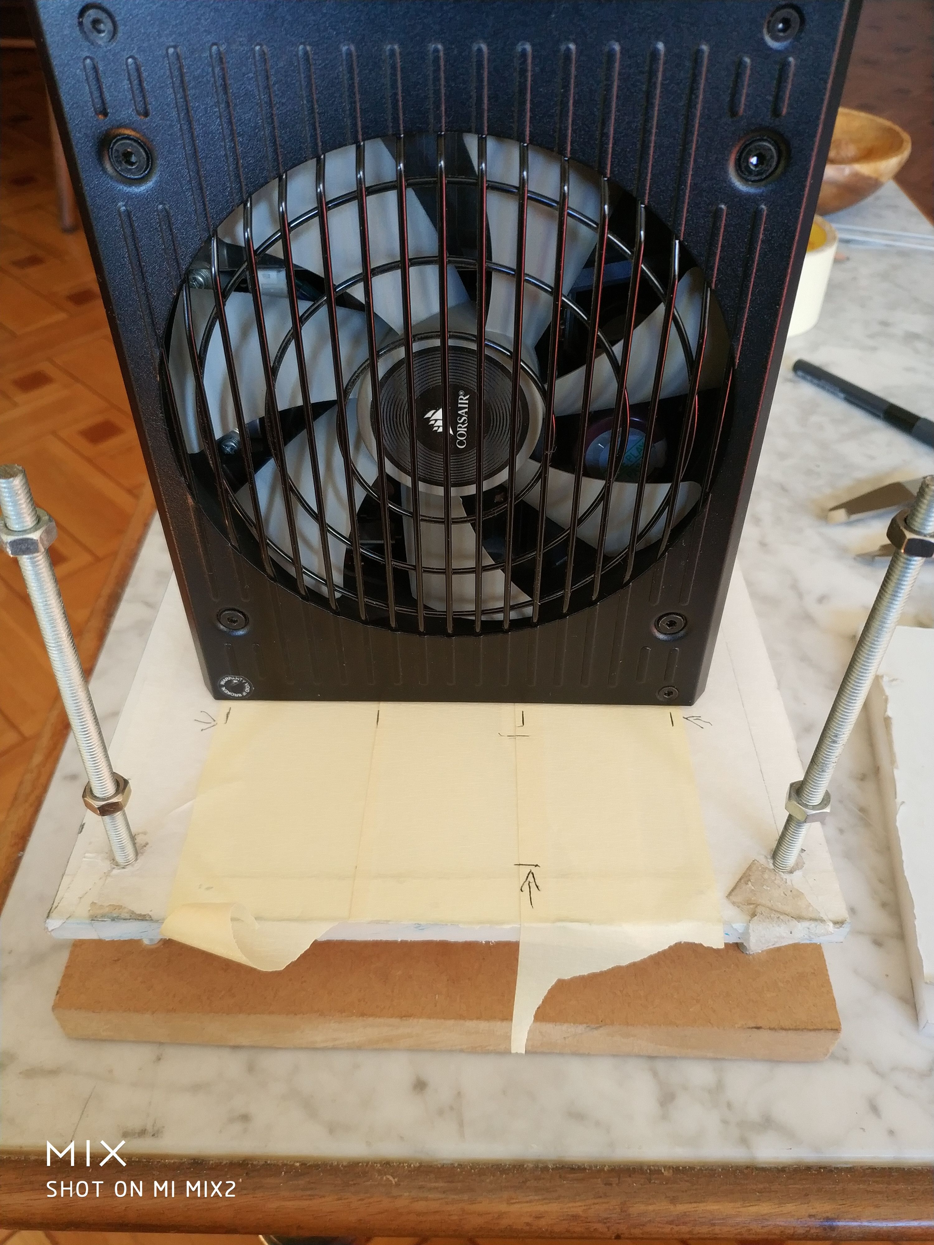
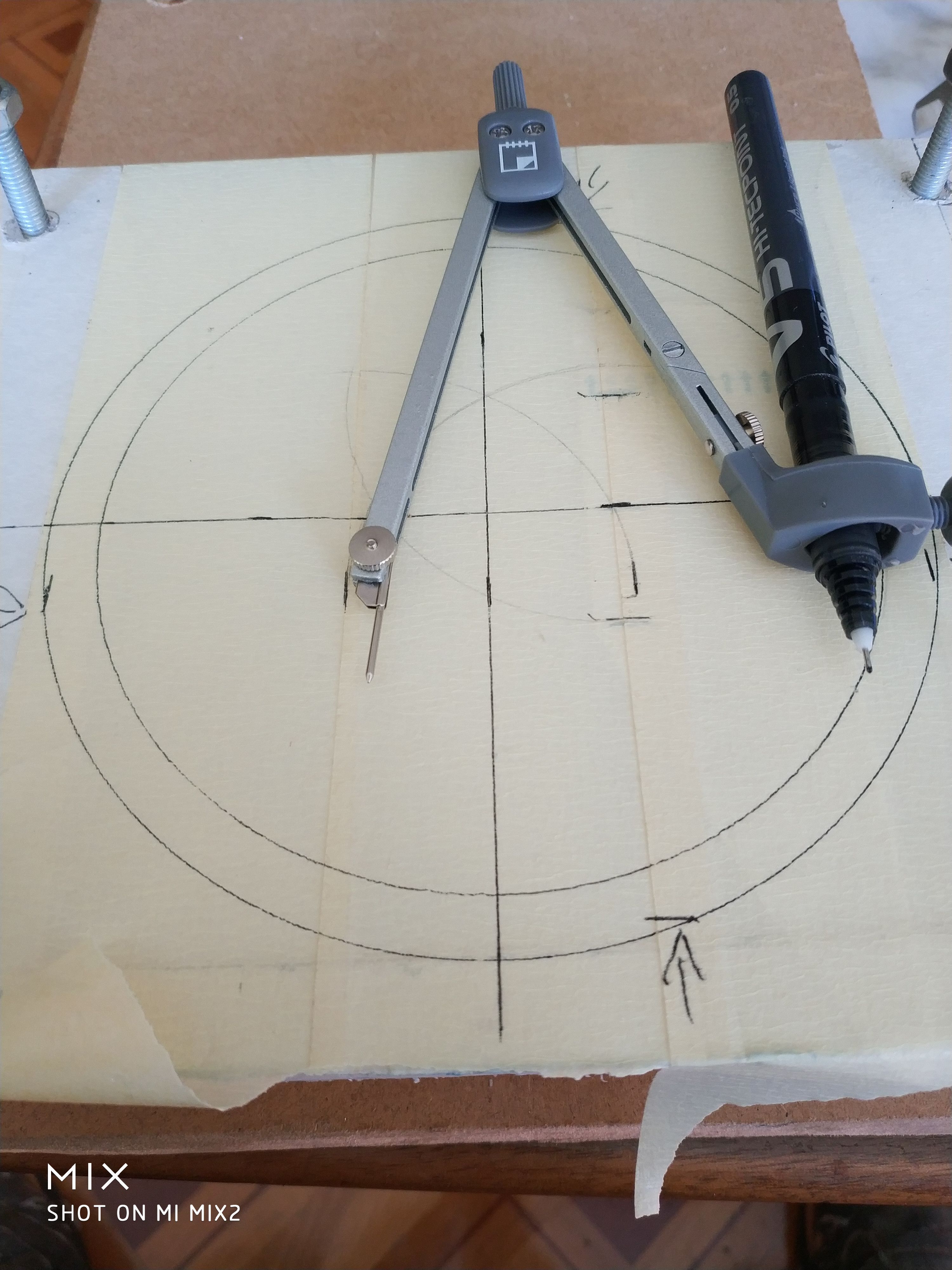
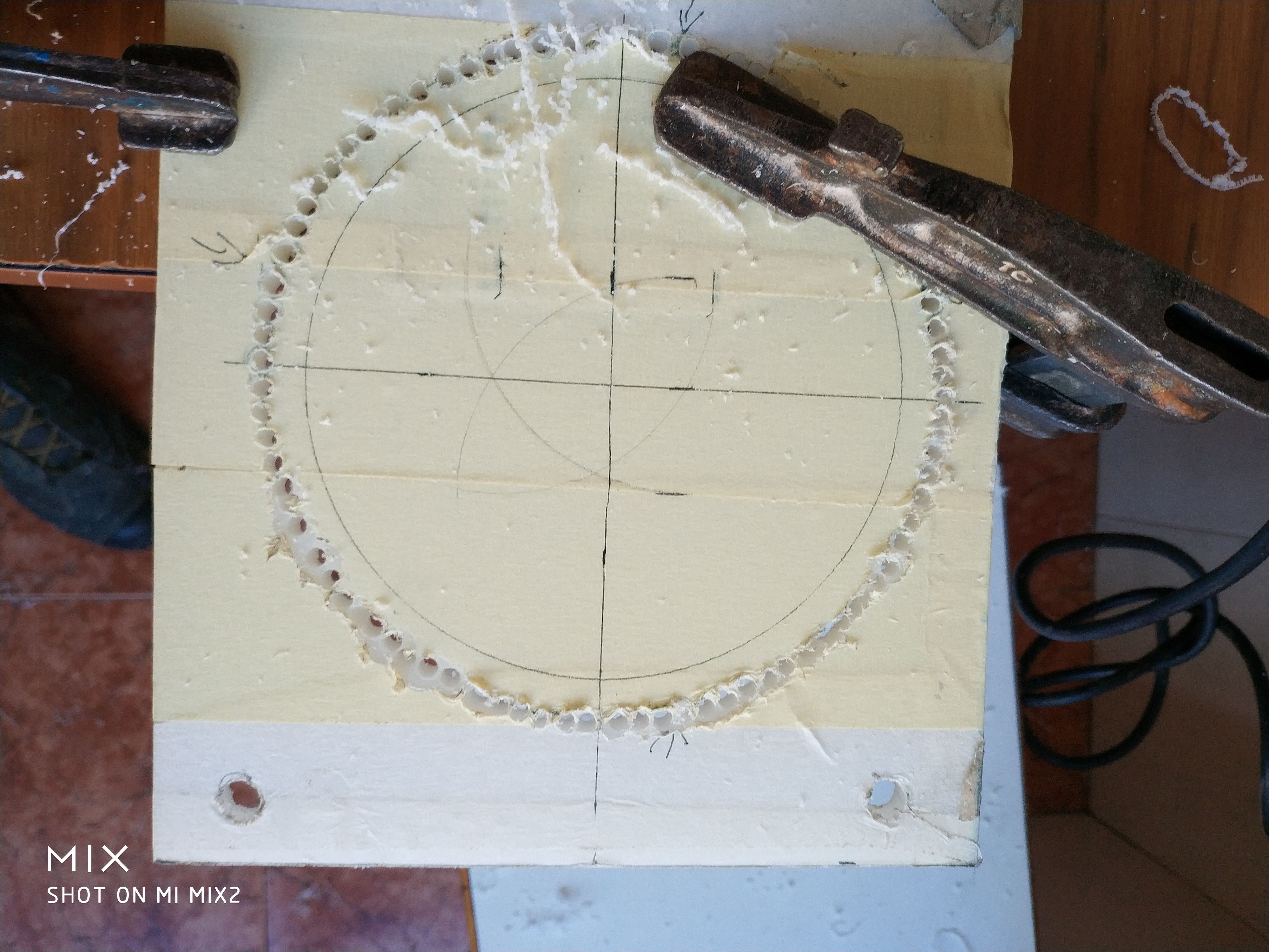
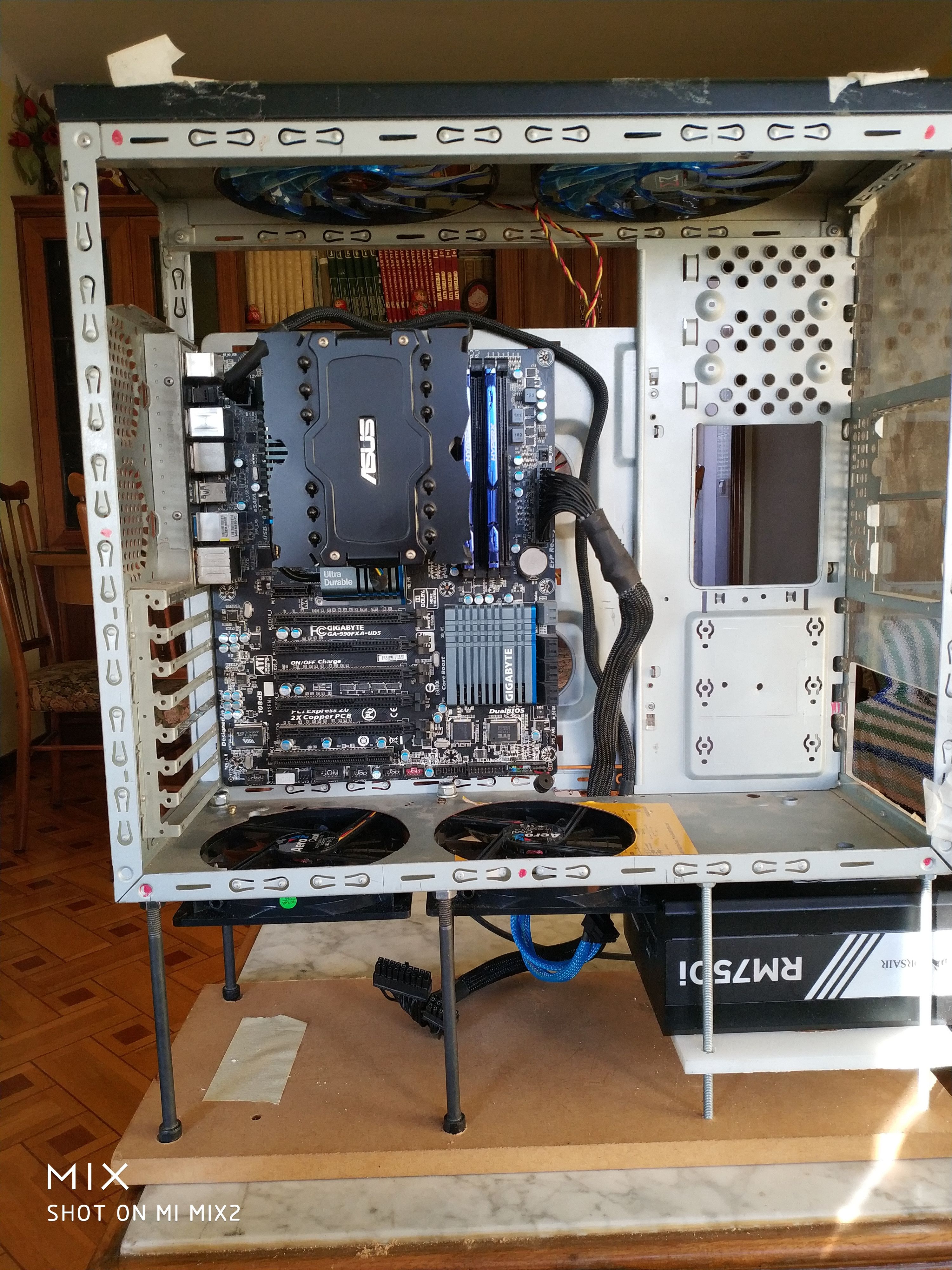
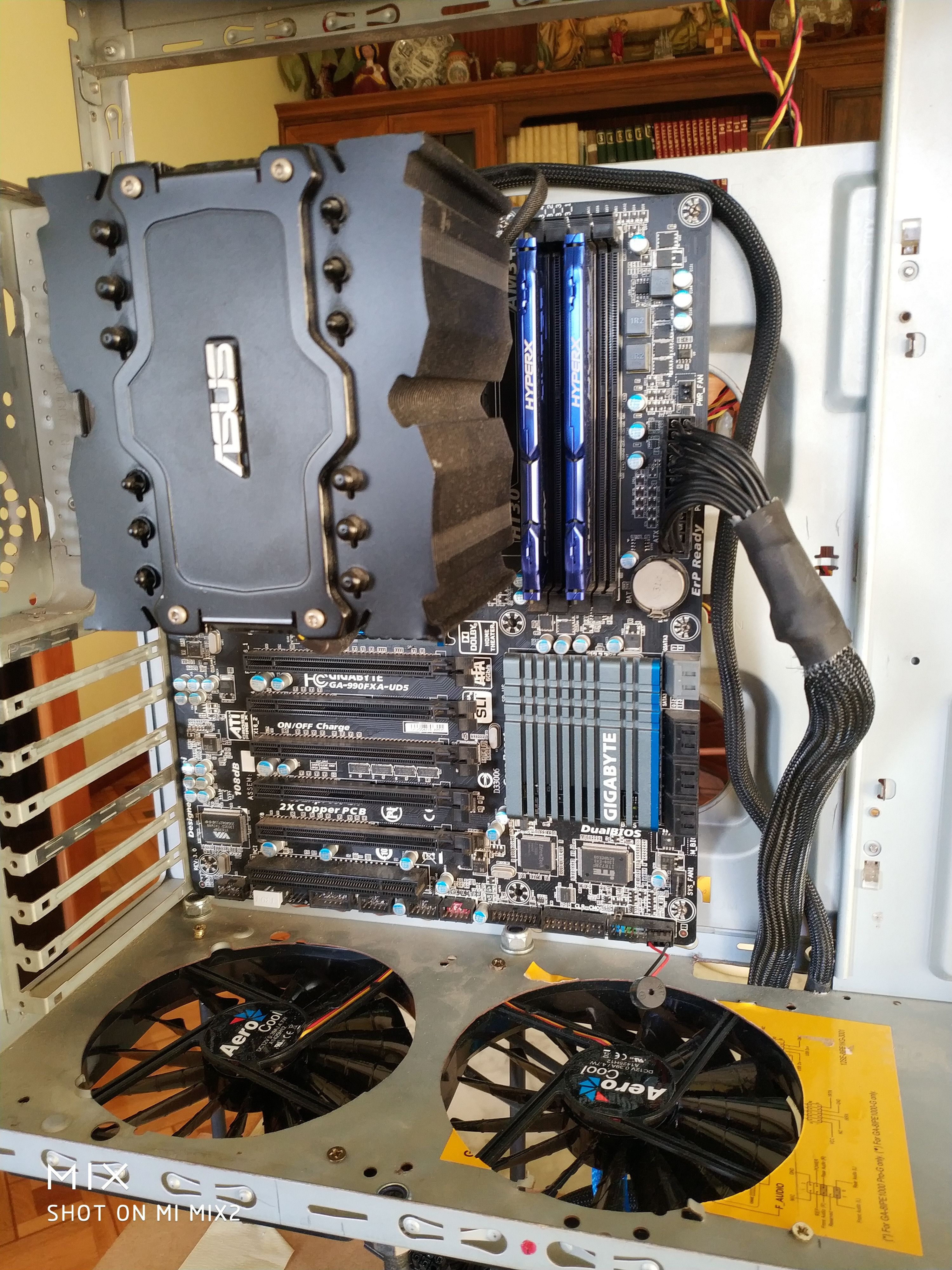
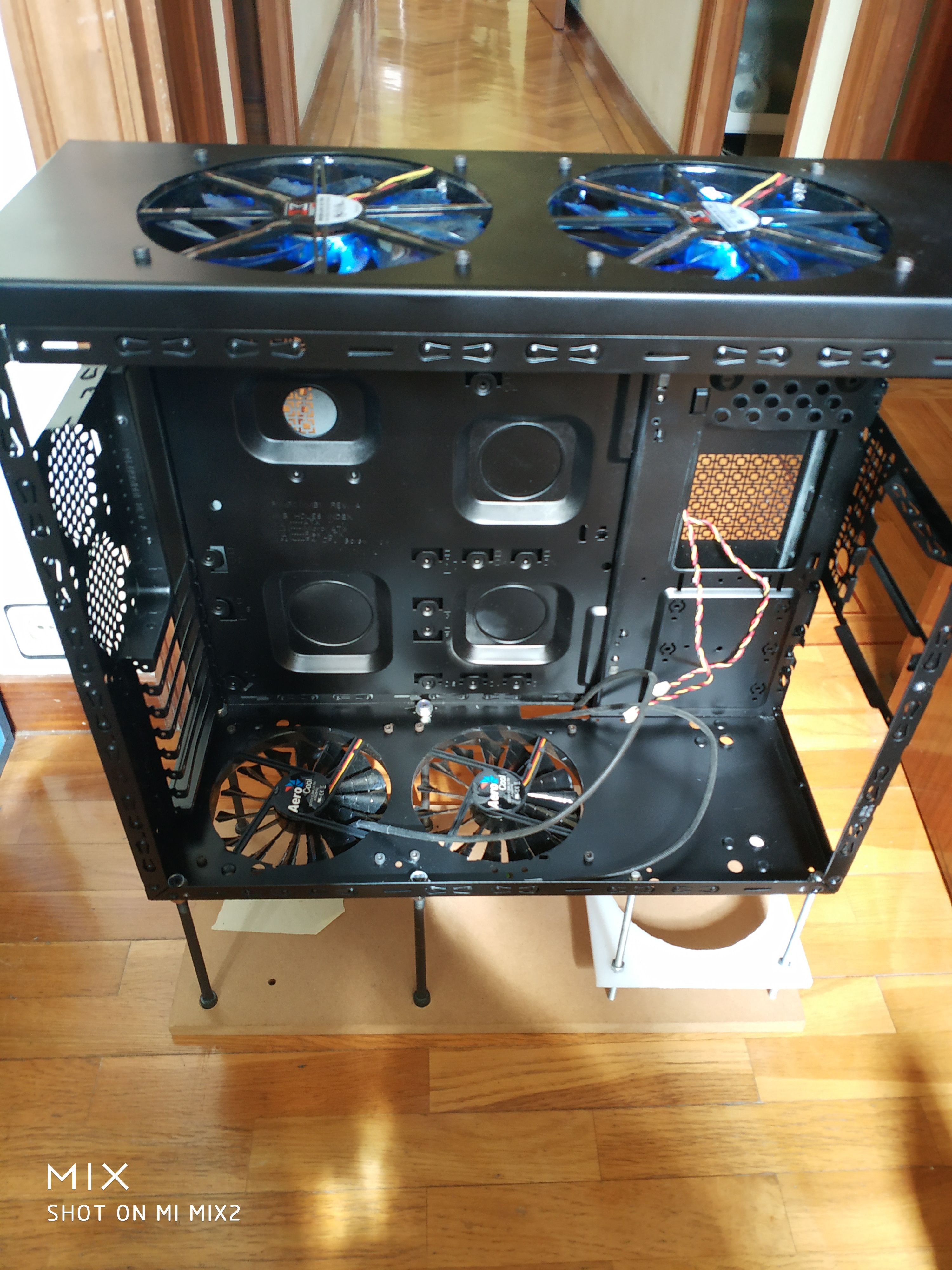
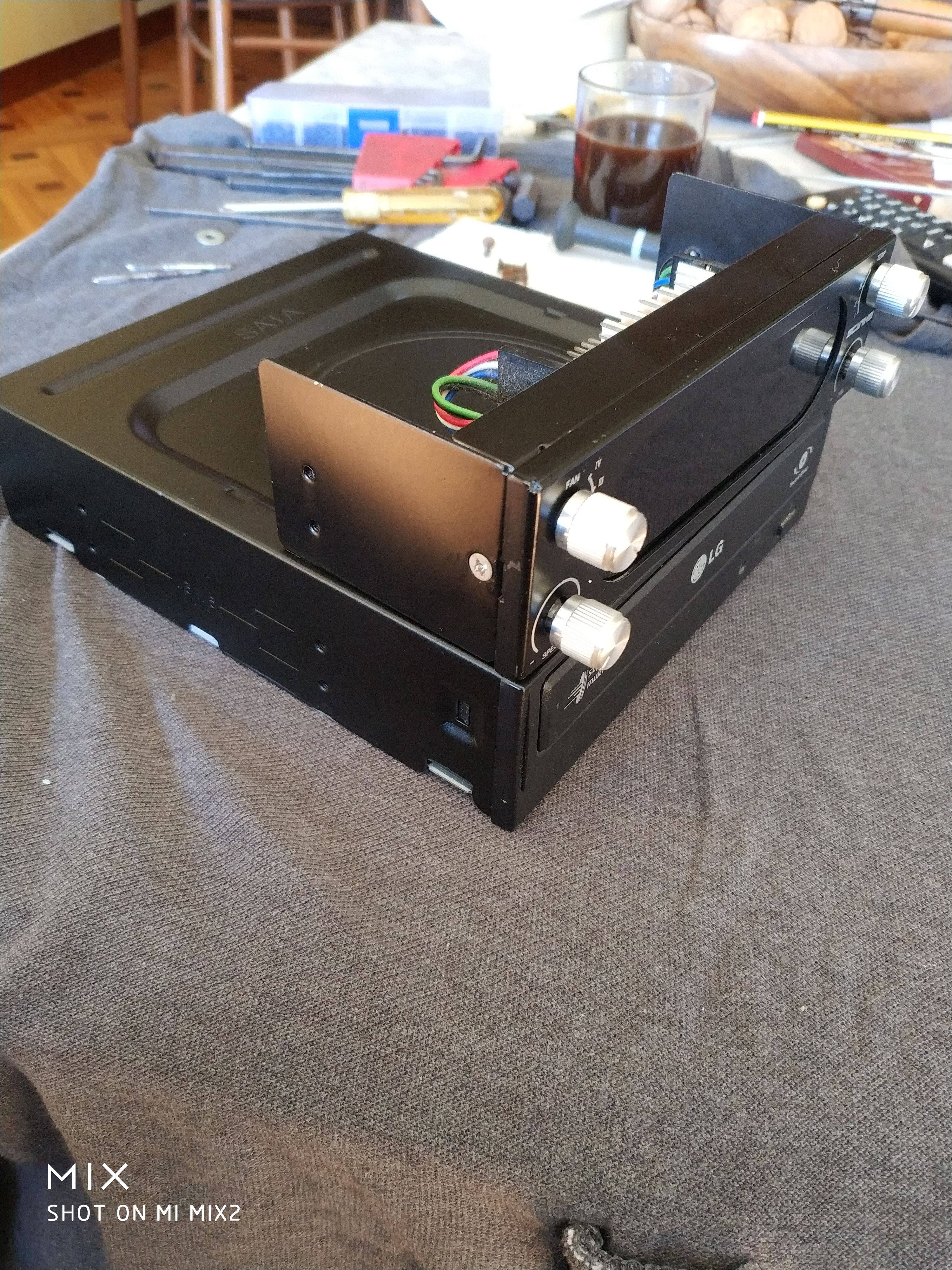
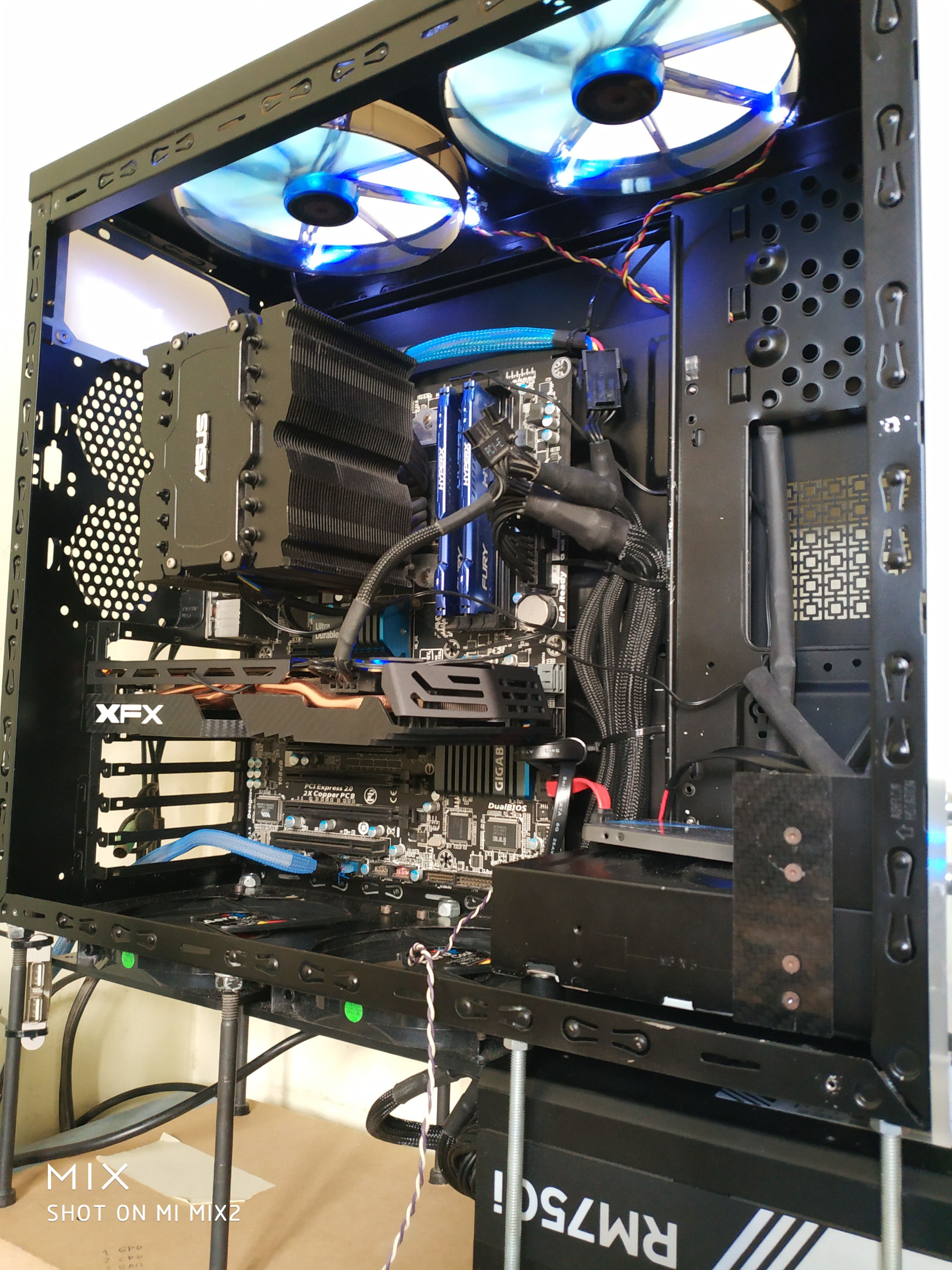
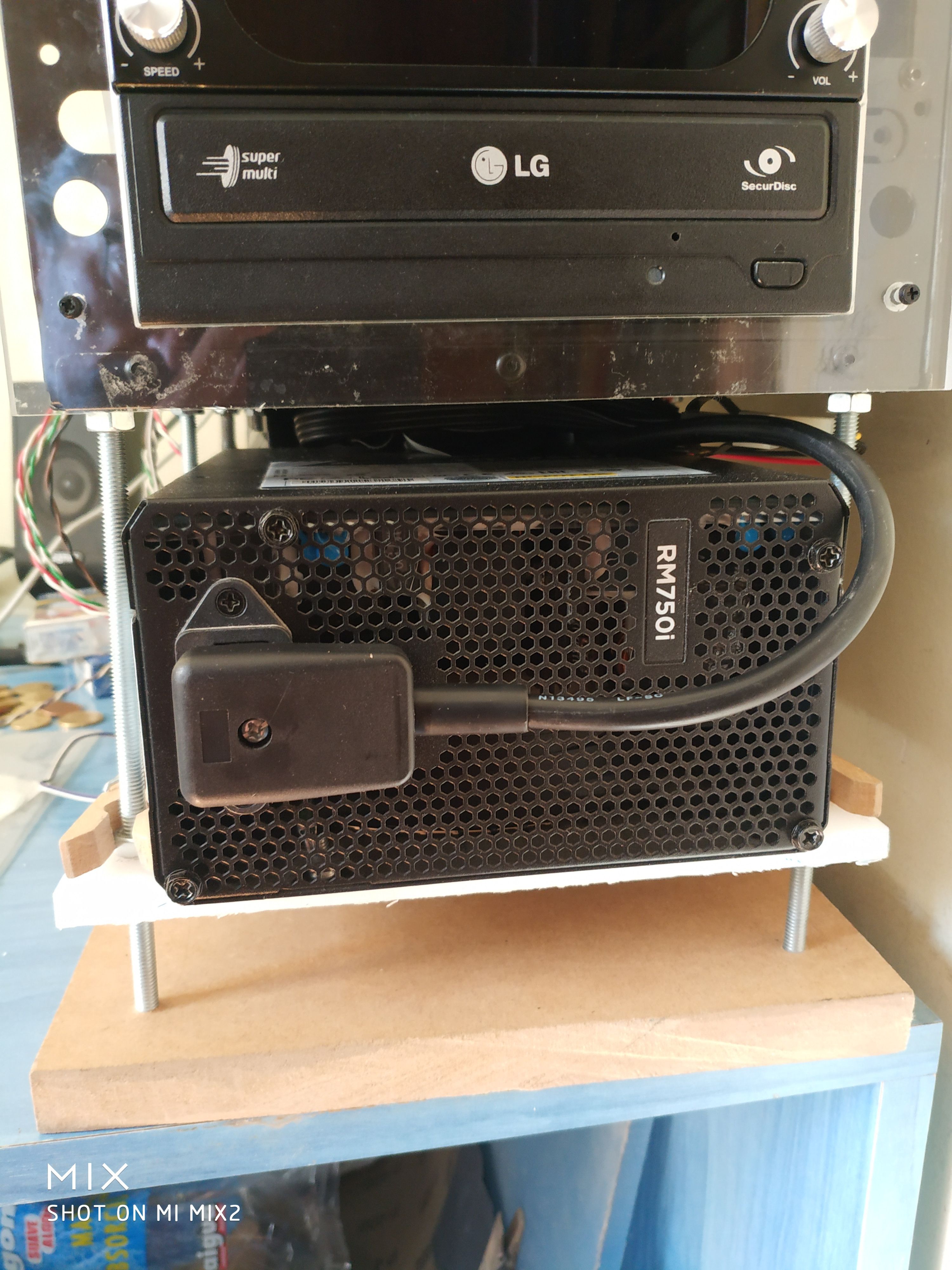
Se realizaron cortes y taladros en metacrilato (plexiglás) para crear piezas personalizadas, como agujeros para ventiladores, soportes para el ventilador de la fuente de alimentación (F.A.), y una base para el disipador. El proceso de mecanizado fue manual y requirió paciencia y creatividad.
3. Problemas Técnicos y Soluciones:
Durante el proceso, surgieron varios problemas técnicos, como la falta de conectores para cableado personalizado y la necesidad de improvisar soluciones para la colocación de cables y componentes. Se utilizaron adaptadores y prolongadores de cables para resolver estos problemas.
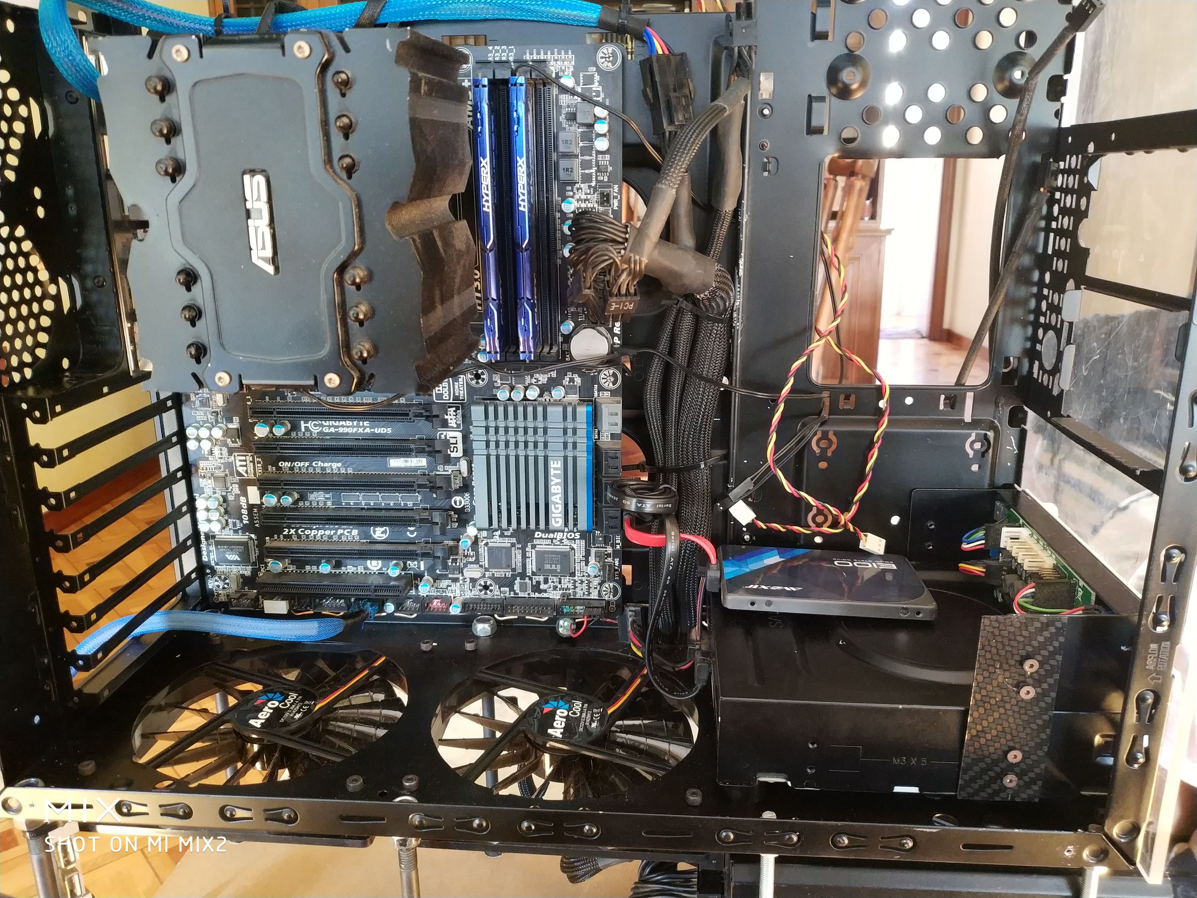
4. Montaje y Pruebas:
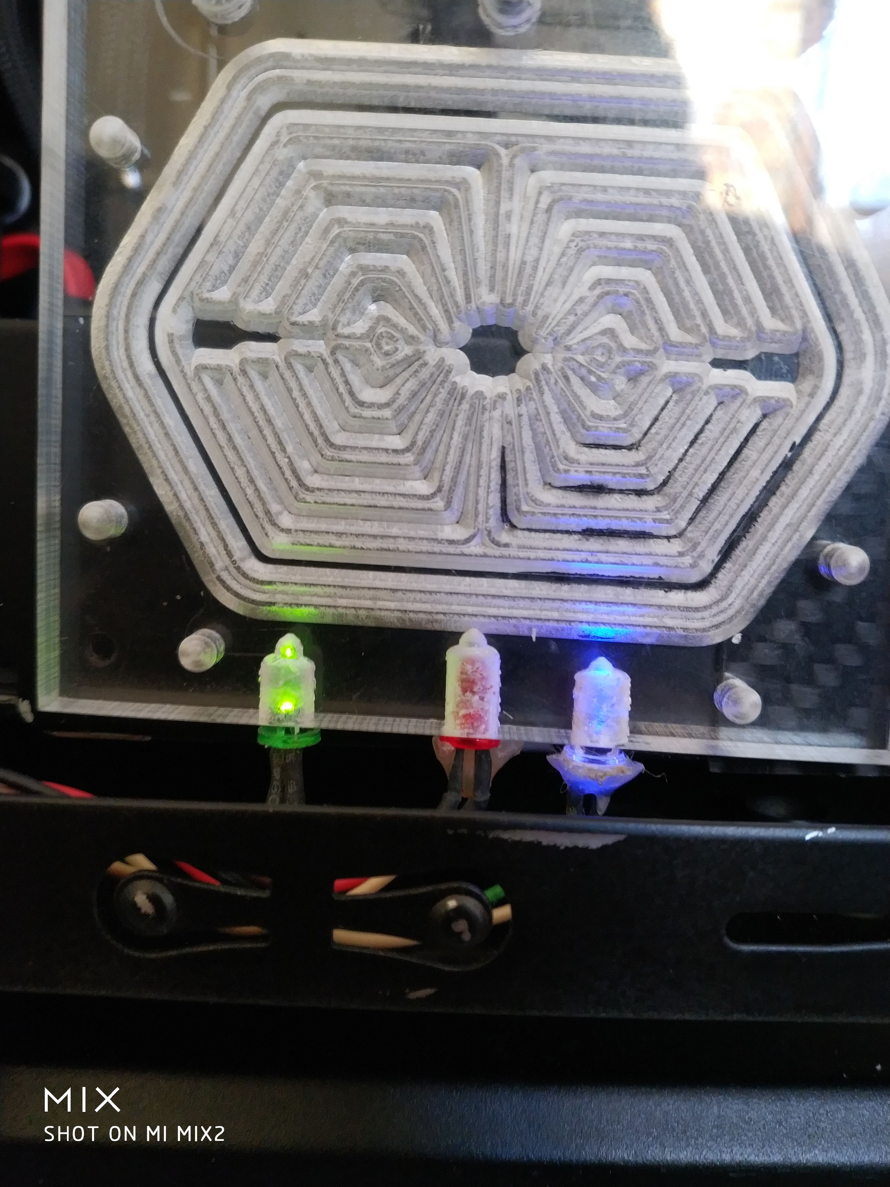
El usuario realizó un montaje preliminar de la torre, conectando todos los componentes y realizando pruebas de funcionamiento. Se encontraron problemas con los LEDs de actividad de la F.A. y del disco duro, que no funcionaban correctamente, lo que llevó a la decisión de no utilizarlos.
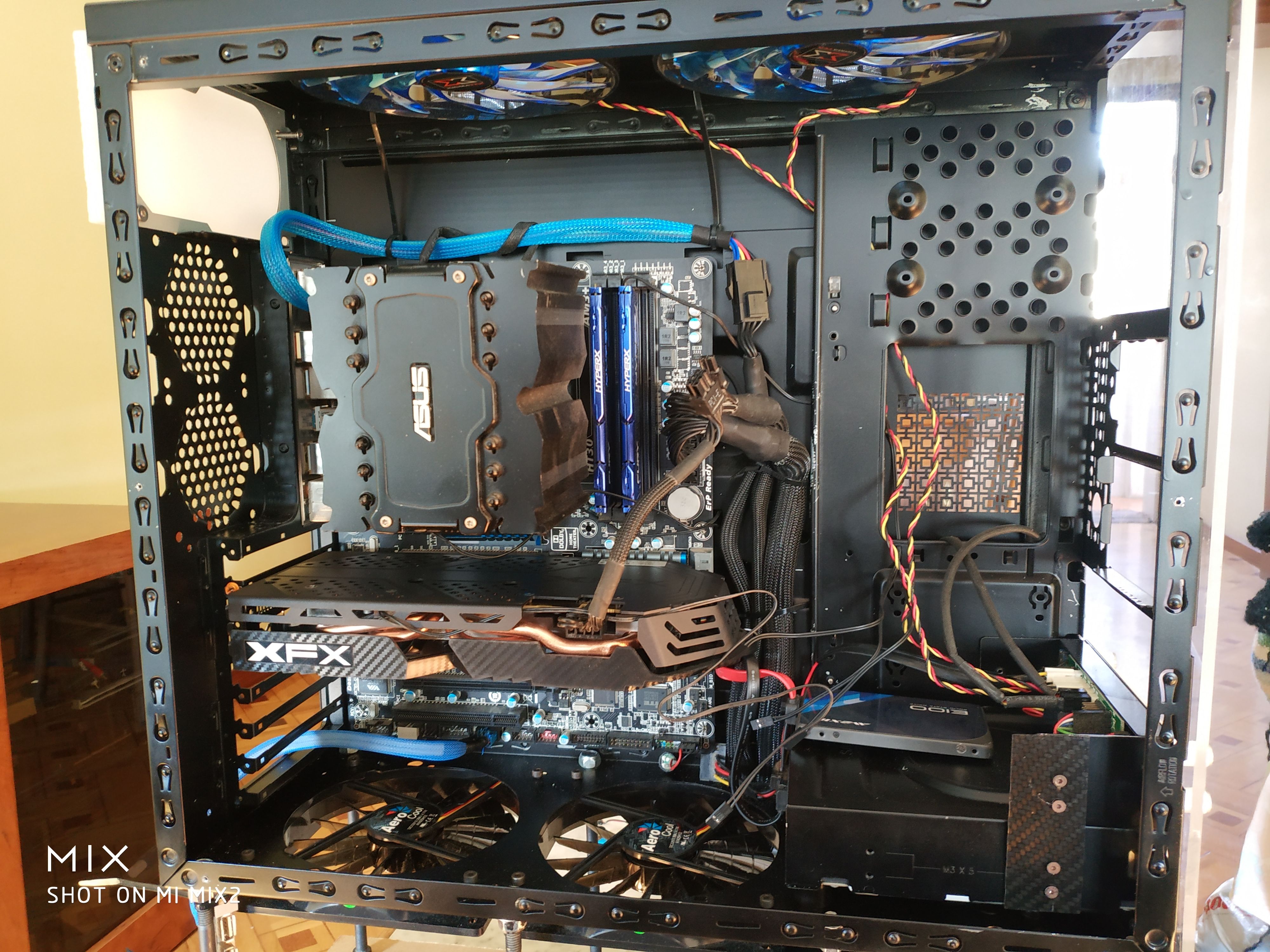
5. Mejoras y Ajustes Finales:
Después de las pruebas iniciales, se realizaron ajustes menores, como la colocación final de los cables y la fijación de los componentes. Se decidió no pintar la base de madera debido a la dificultad y el tiempo que llevaría, con la intención de reemplazarla en el futuro.
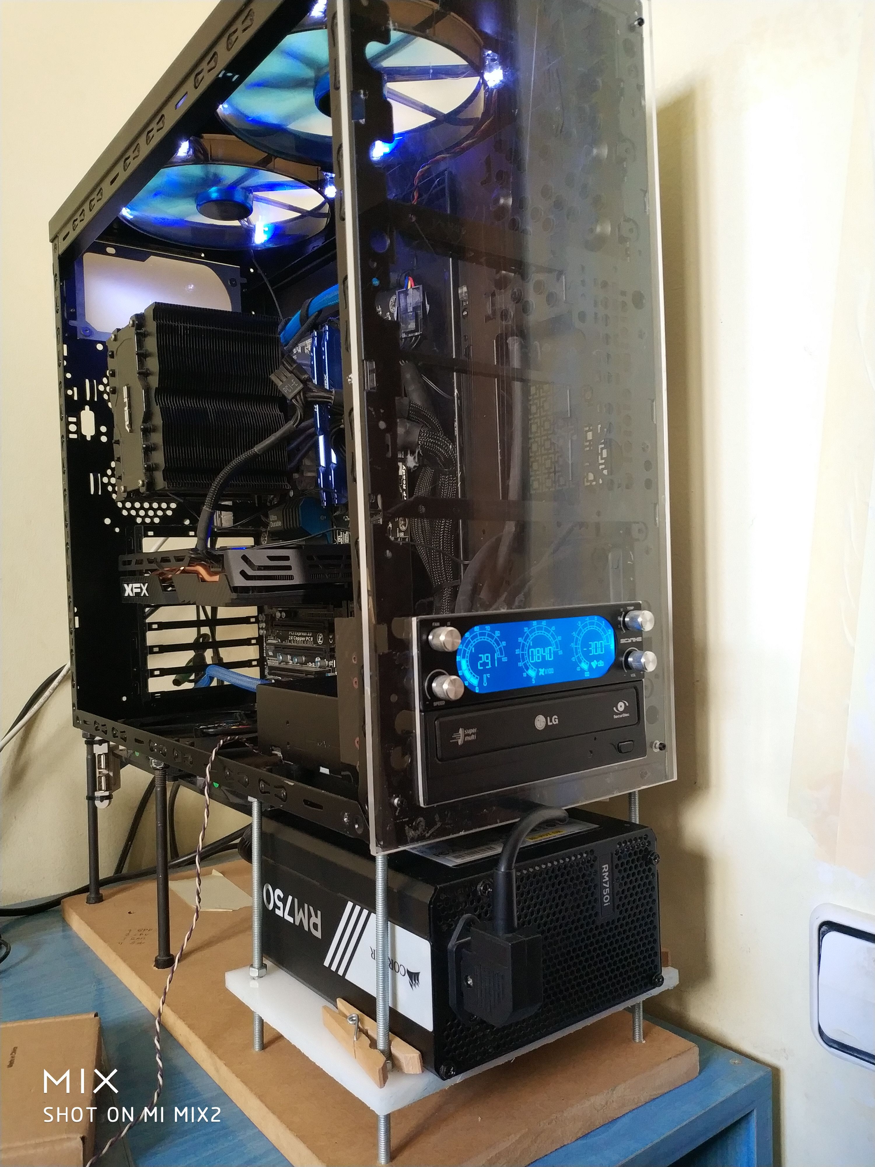
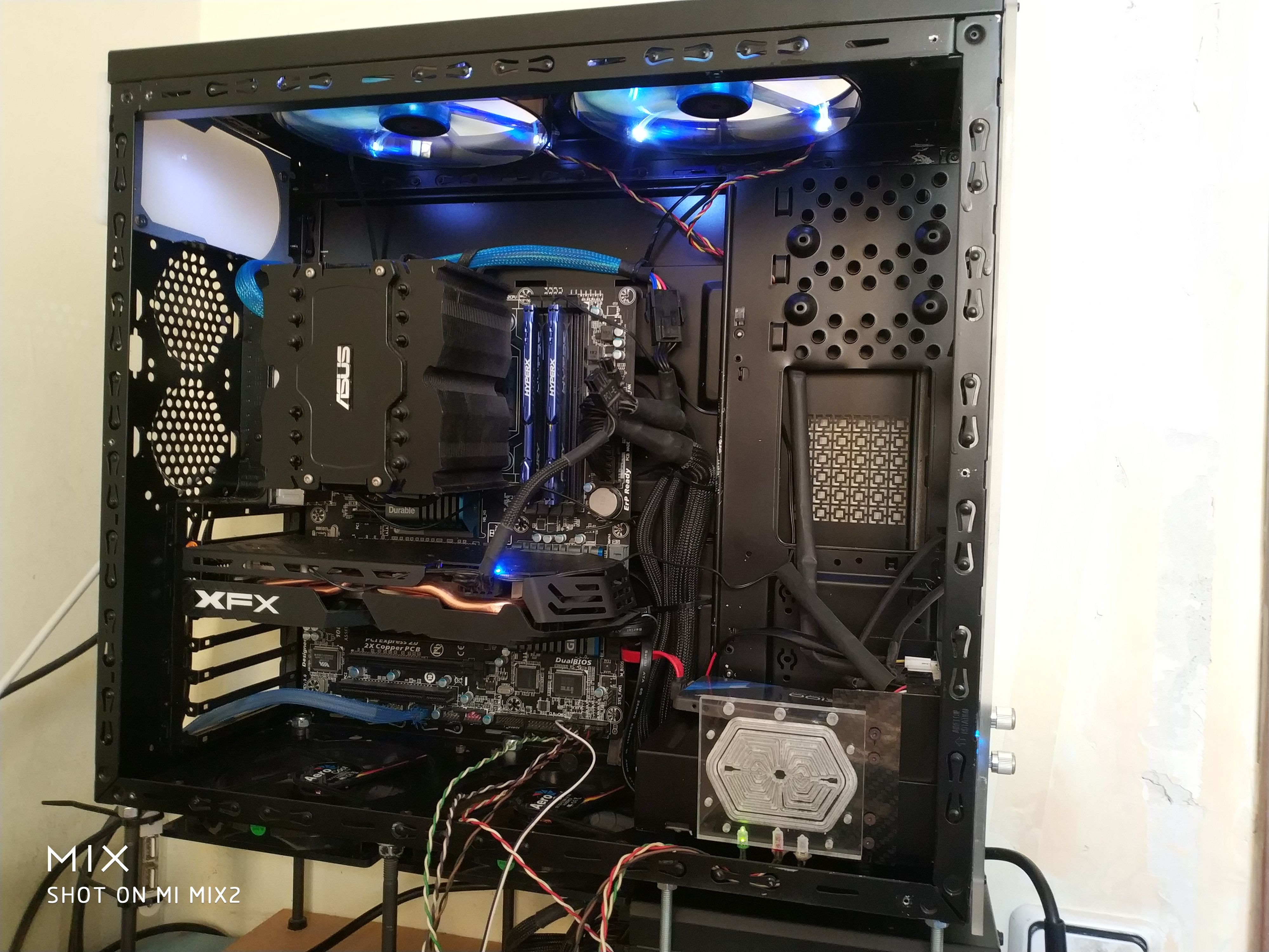
6. Resultado Final:
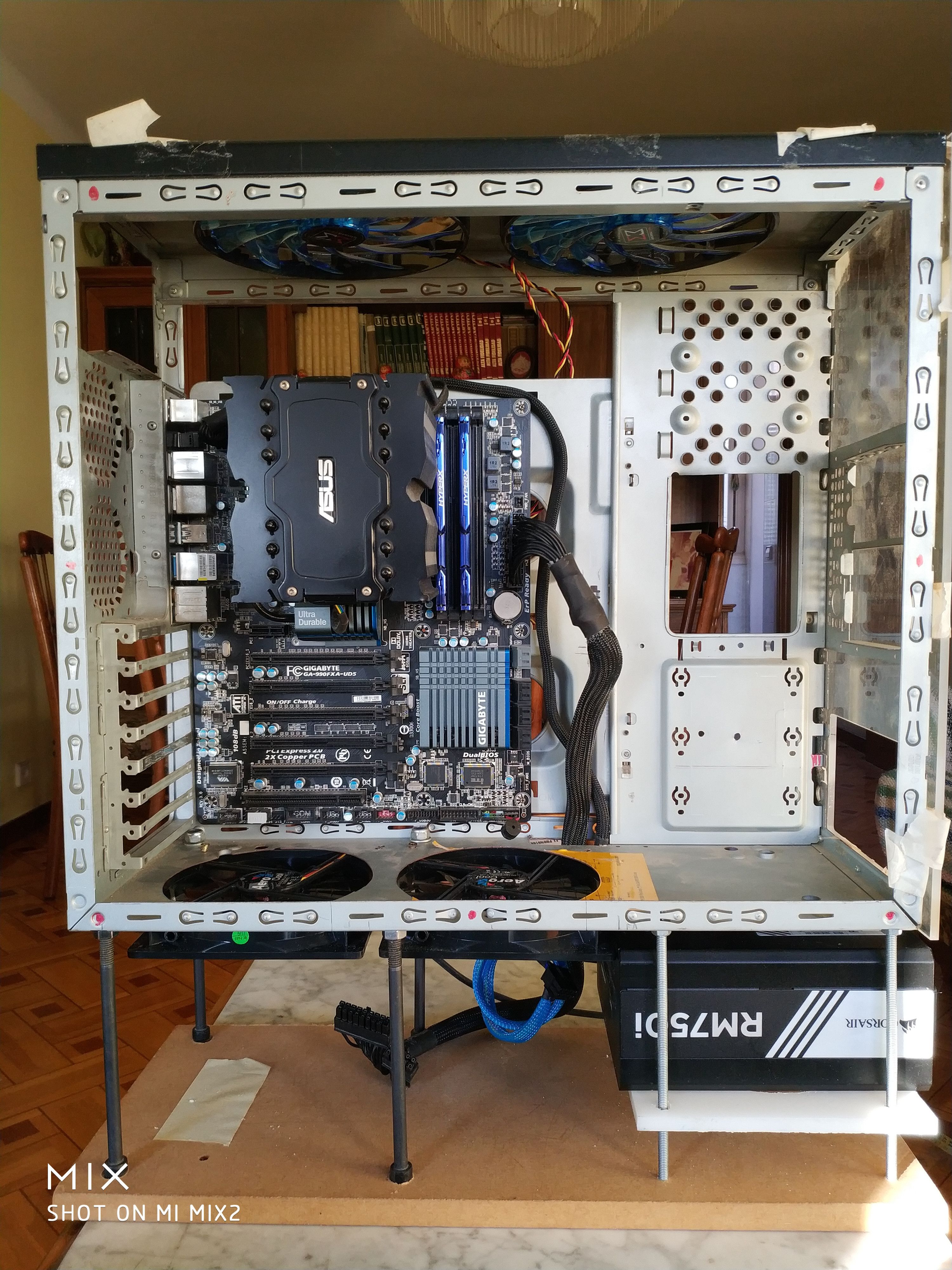
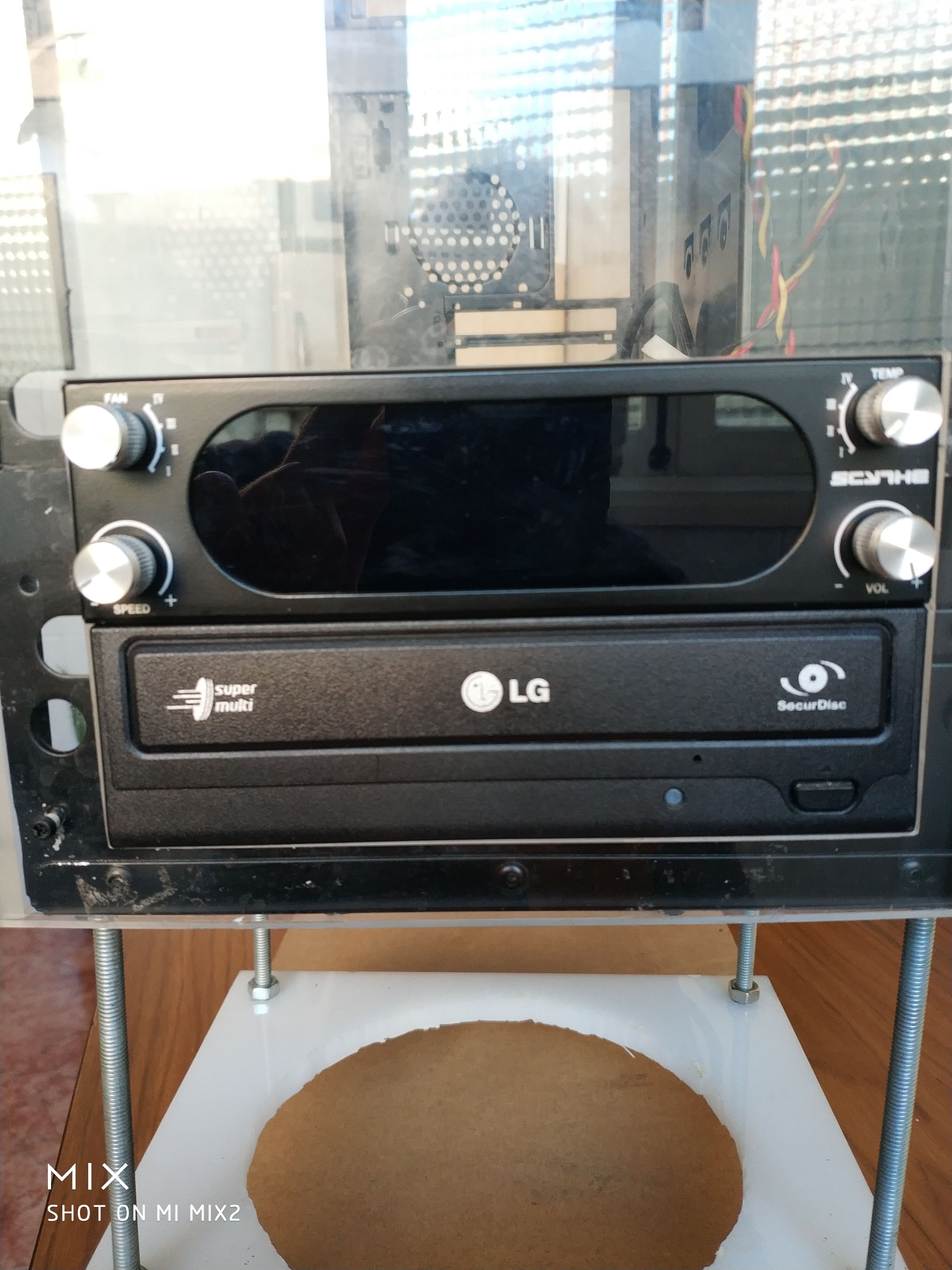
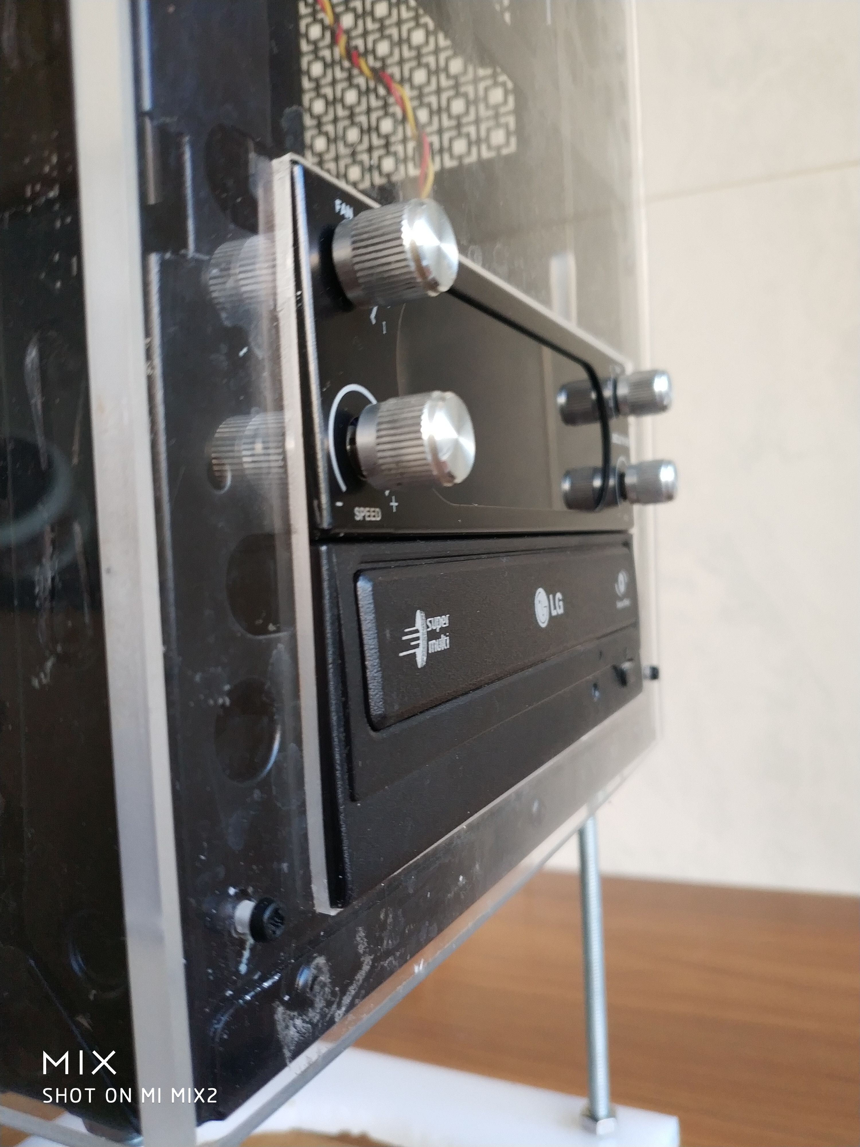
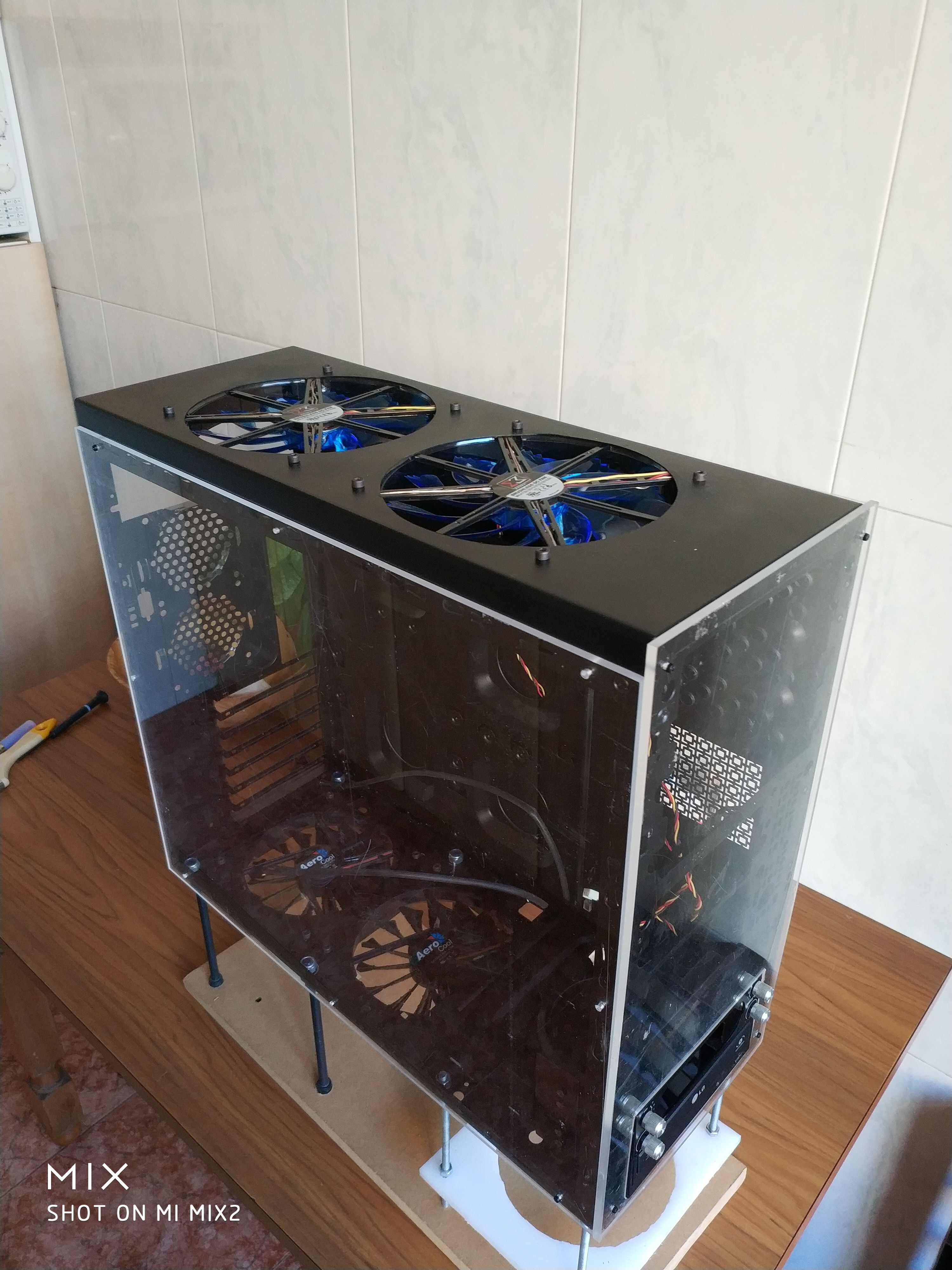
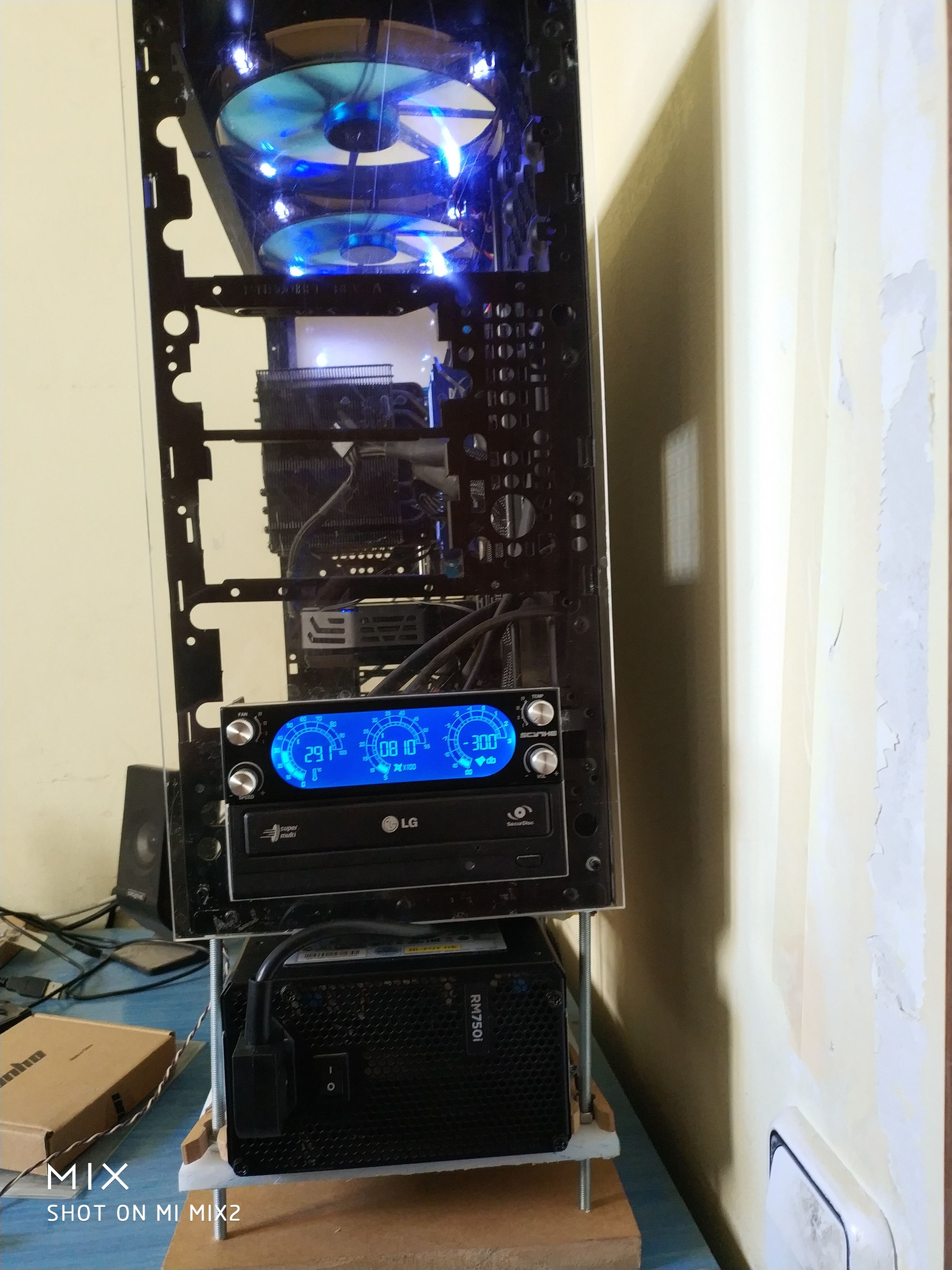
El resultado final es una torre con una estética mejorada y una ventilación más eficiente. Aunque no se alcanzaron todos los objetivos iniciales debido a limitaciones de tiempo y recursos, el usuario considera que el resultado es satisfactorio y planea realizar mejoras en una versión posterior (REV 0.1).
Imágenes y Detalles Técnicos:
El usuario compartió varias imágenes del proceso, mostrando cada paso y el resultado final. También describió los materiales utilizados y las herramientas improvisadas para superar los desafíos técnicos.
Conclusión:
Este proyecto es un ejemplo de cómo con creatividad y paciencia se pueden lograr mejoras significativas en una torre de PC, incluso con recursos limitados. El usuario aprendió mucho del proceso y planea aplicar esas lecciones en futuras modificaciones.
-
¡Esta publicación está eliminada! -
¡Esta publicación está eliminada! -
It looks great, I'm a big fan of this type of mods, a bit crazy and with ingenuity, in the end the result can be really good if you dedicate the necessary time and affection. Looking forward to seeing how it continues, thanks for bringing mods in these times, a section that is quite forgotten and that for me personally was one of the key factors to get into this world. Best regards!>> i7-2600K Sandy Bridge @4.4GHz || Noctua NH-D14 || ASRock Z77 Extreme4 || 4x8Gb G.Skill Ripjaws X DDR3 1600MHz || XFX RX 5700 XT 8Gb || SSD Samsung 850 PRO 256Gb & 850 EVO 500Gb || WD Caviar Green 1Tb || Barracuda 1Tb || Corsair TX650 V2 || M-Audio Fast Track Pro || KRK RP8 RoKit G3 || BenQ GW2750 27"
>> Athlon 64 X2 5600+ Brisbane @2.9GHz || Gigabyte GA-M61PME-S2 || 2x2Gb DDR2 Kingston 800MHz || Sapphire Radeon HD 5850 Xtreme 1Gb || Maxtor 320Gb SATA2 || OCZ ModXStream 500W Modular || TEAC PowerMax 120/2 || Acer X243w 24"
>> Intel Core2Duo E6600 Conroe @2.4GHz || Asus P5N32-SLI SE DELUXE || 2x1Gb DDR2 Kingston 800MHz || Asus nVidia GeForce 9800GT 1Gb GDDR3 || Seagate Barracuda IDE 80Gb 7200RPM || Linkworld LPK12-35 450W -
@Sylver
thanks.
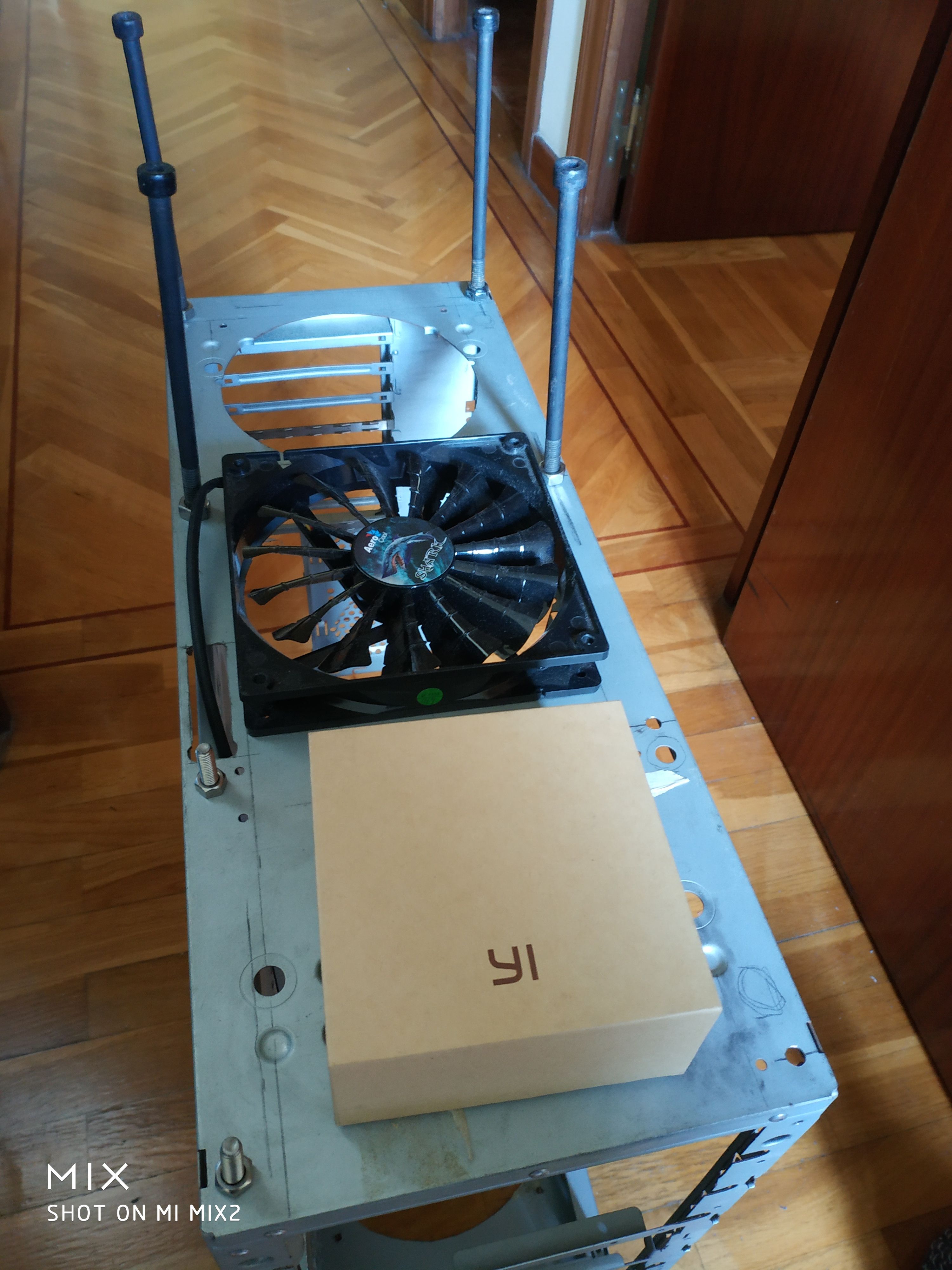
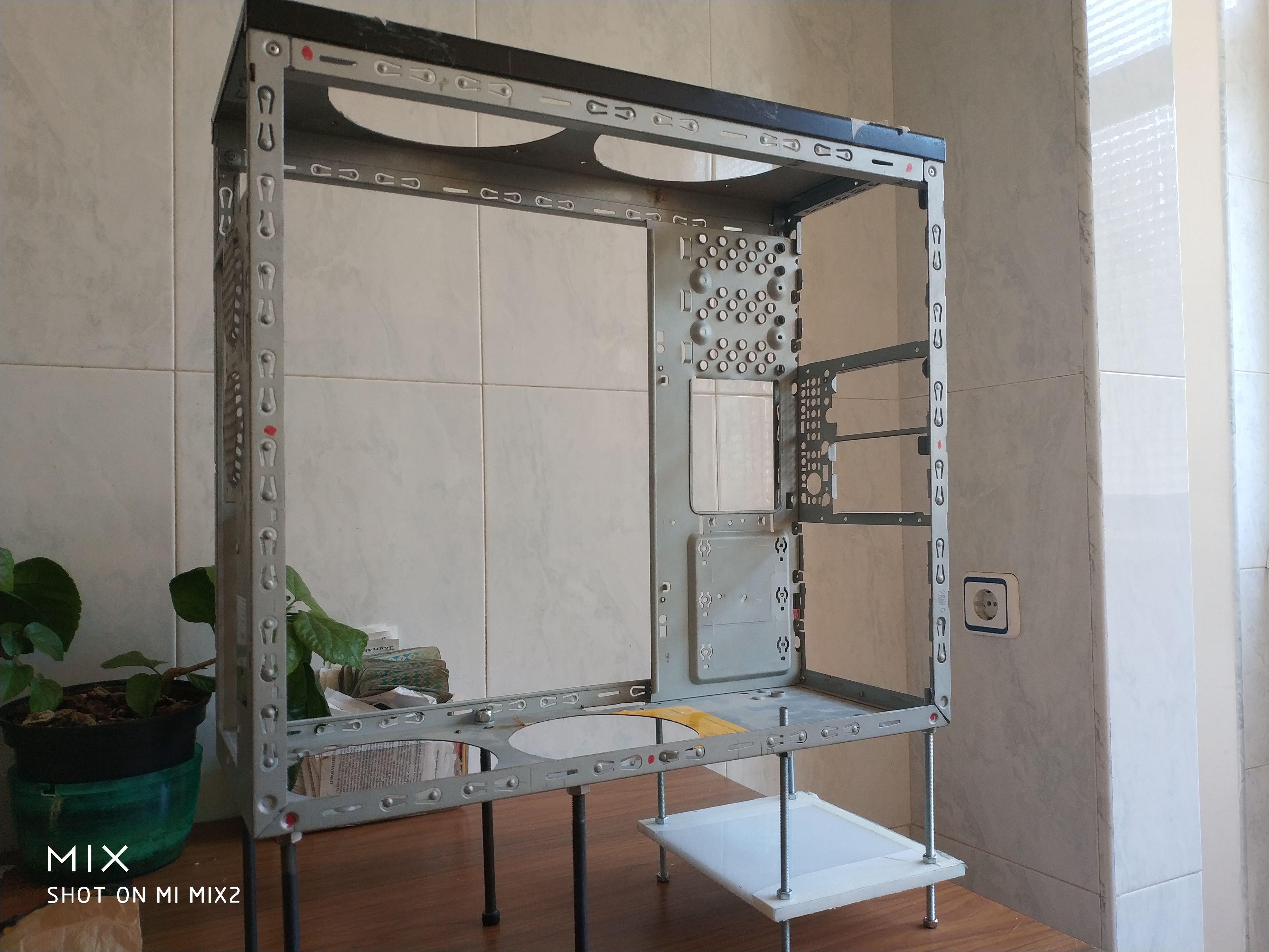
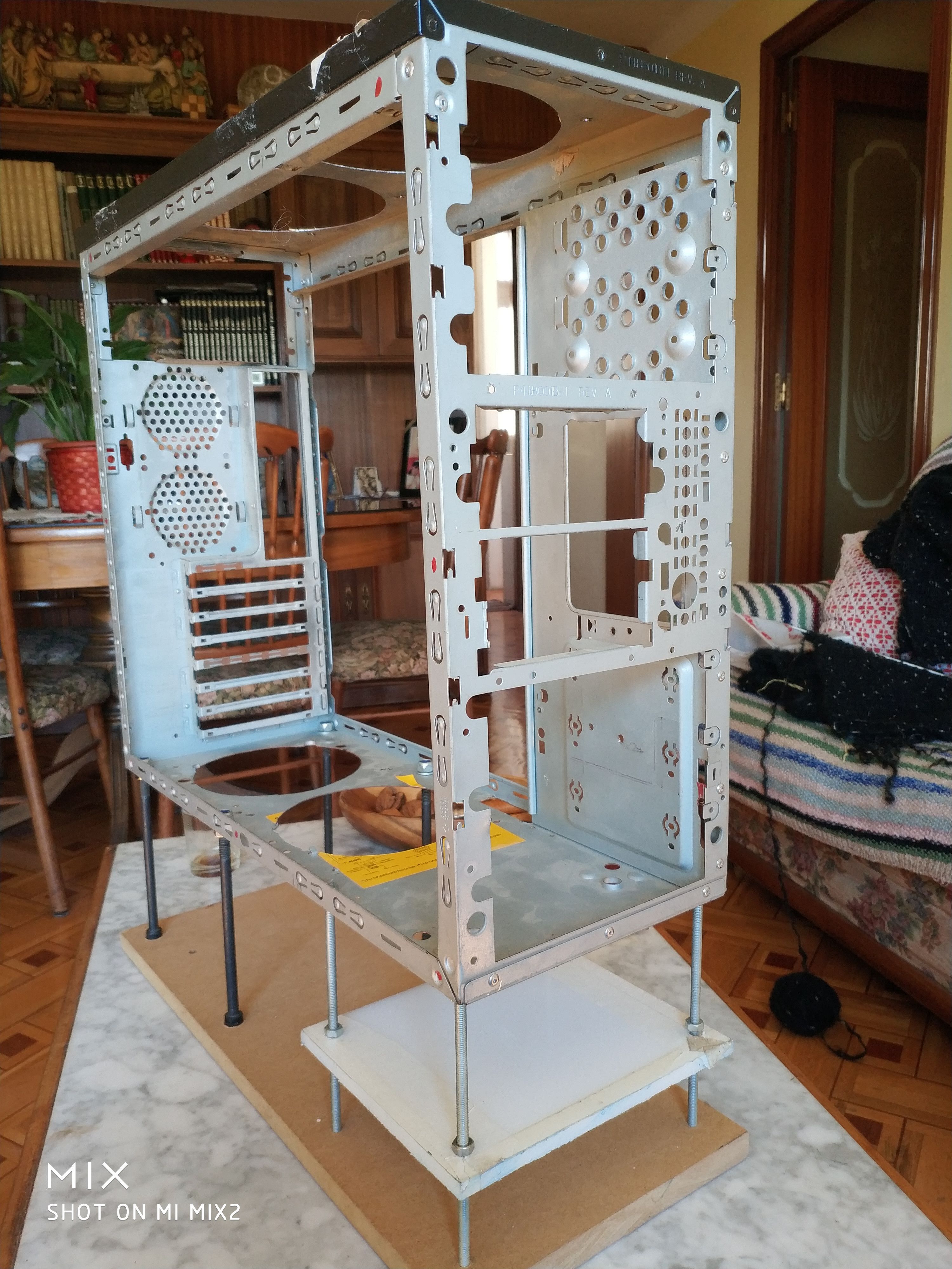
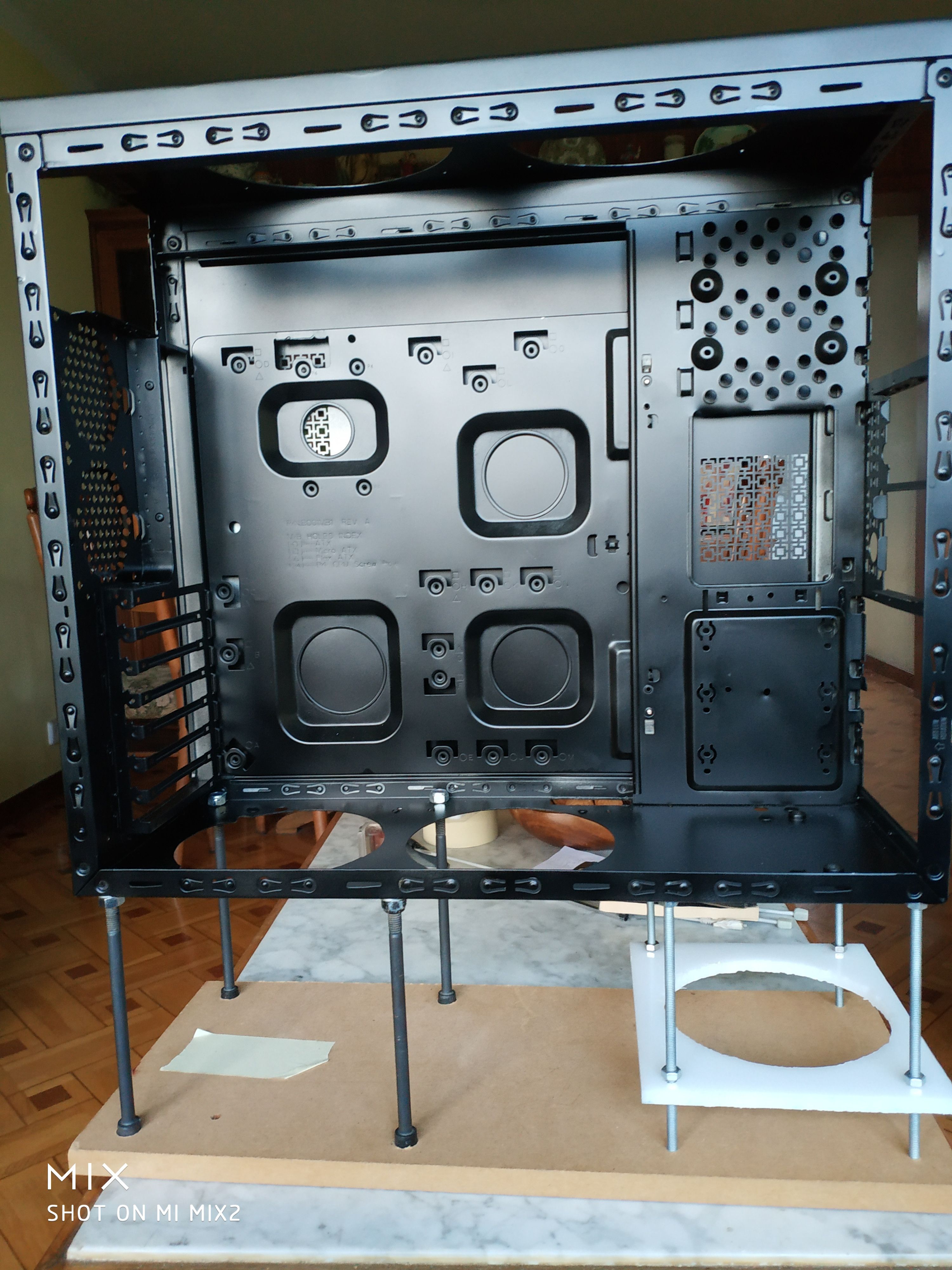
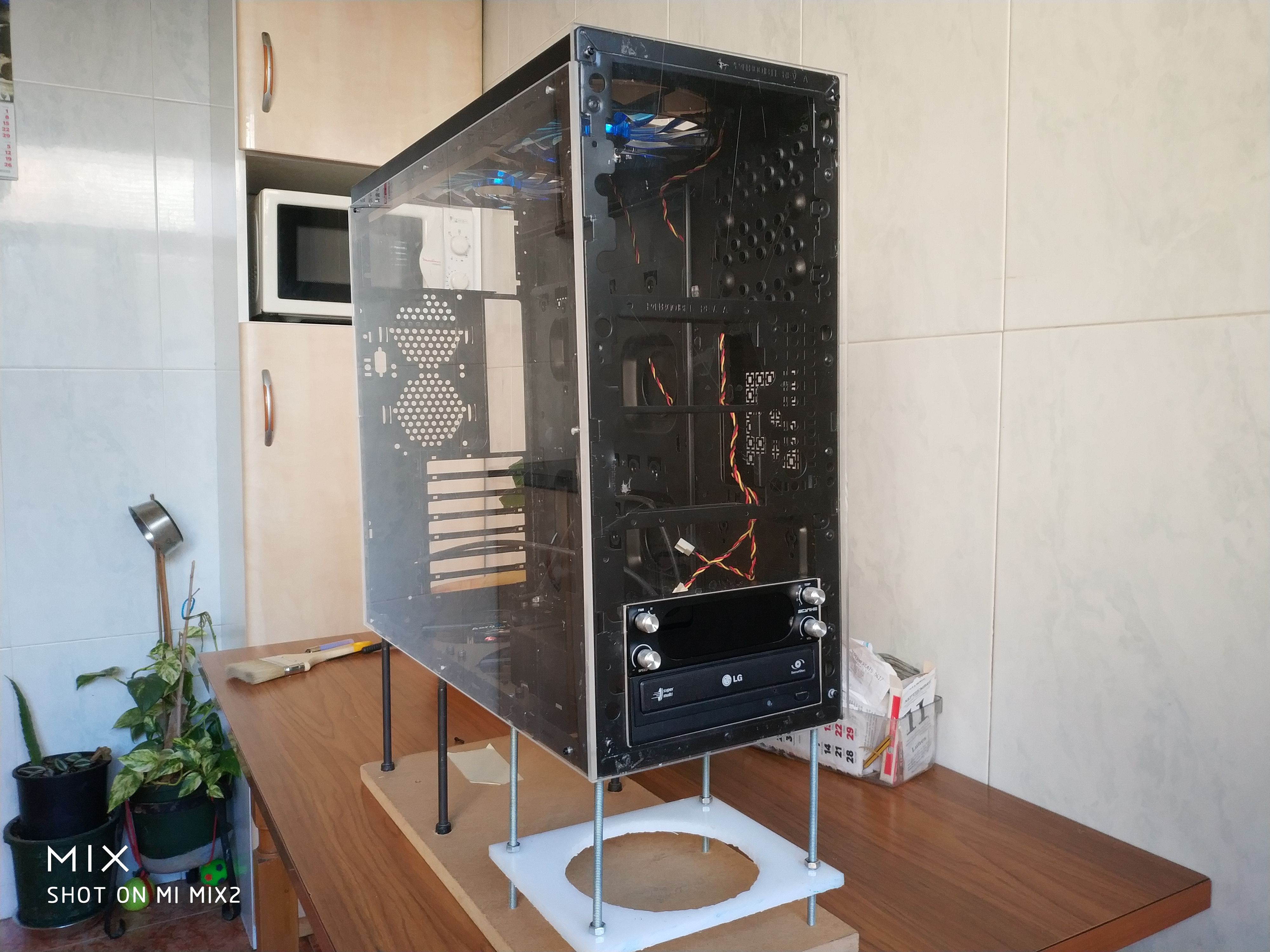
the truth is that I am reusing a material that is a bad thing the threaded rod comes from a pringels antenna ( family size ) that I converted into an mtb wheel truing project.
and now you see... for the pc mod
I already know that some will be thinking that the threaded rods on a table is a bad idea... and it is.
that's why there is a piece of MDF wood underneath that I have lying around.
and I can promise and I promise that when I finish and this ends... I will redo it in conditions.
for example the threaded rods on the paper iva lined with 15mm aluminum tube.
details that I can't get now, but let's hope that this is the only bad thing that this crisis brings us
greetings and calm -
Any guide for making custom cables?
In my case it's the opposite, they are all long except for the 8-pin one from the motherboard and I don't plan on cutting it.
Regards -
@Clipper No idea, I would do it as before, with what I have at home, splicing and taping if necessary.
It's coming out great, keep it up!
Best regards!
-
Well...
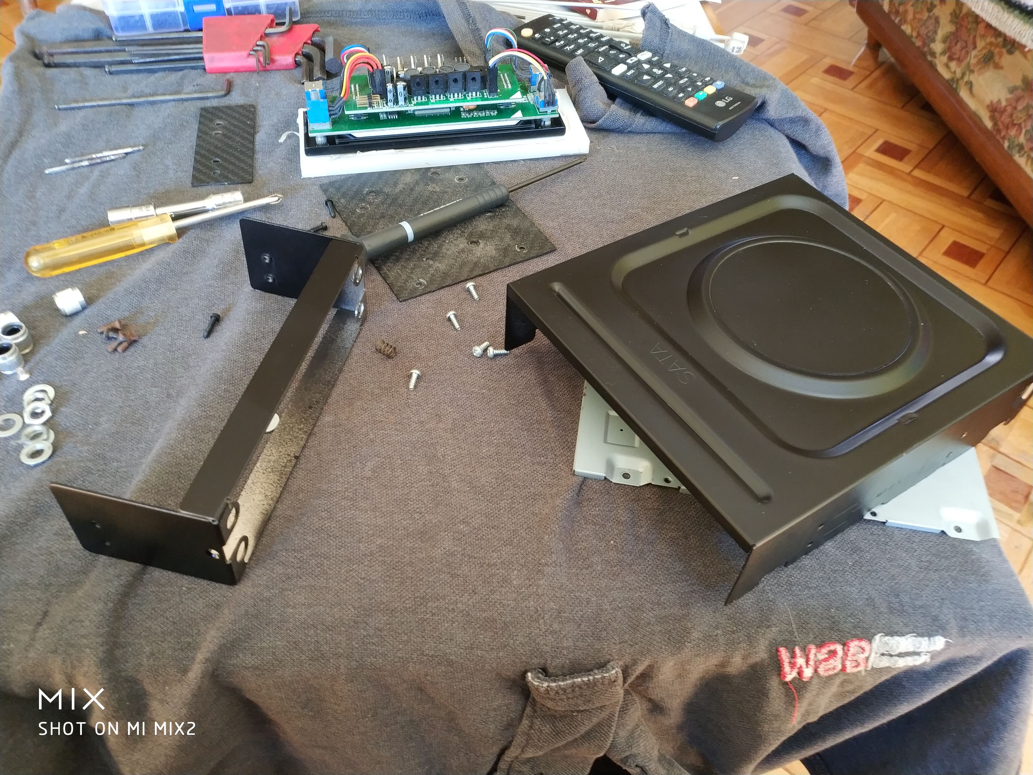
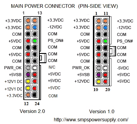
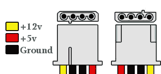
Easier, can someone tell me exactly the name of the connectors (pins to solder) of the F.A cables
Thanks and regards -
Please correct me if I'm wrong:
20/24 pin connector
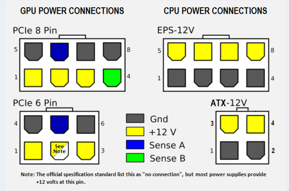
Extra connectors for CPU and GPU
5/12V Molex
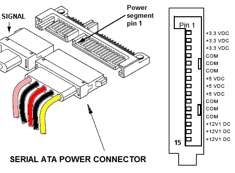
SATA power
Toda la actualidad en la portada de Hardlimit
Mis cacharros -
@cobito said in an old project:
If someone can complete/correct me if I'm wrong:
20/24 pin connector
Extra connectors for CPU and GPU
5/12V Molex
SATA power
Thanks but that's not it.
What I'm looking for are the pins to solder and make new cables.
But I can't find them.
Thanks -

the name of that connector is what I'm looking for, to search for it on the internet.
I have found plastic connectors, (at a reasonable price) but without the pins
link text
link text
for the covers, a paragliding /parachute rope is used. which is called 3mm paracord (about 9€ 20 meters)
regardsSolved.
It is the 5557-R. And the 5557. of 4.2 mmRegards
-
Any recommendations for pushbuttons, surface-mount (the typical ones with a nut/screw behind) for power/reset.
And does anyone know the output voltage of the M.B on the connectors for the leds (the typical ones for hard drive and power.
Regards -
What a great job, congratulations.
-
Simply brutal, it looks scary @Clipper, congratulations.
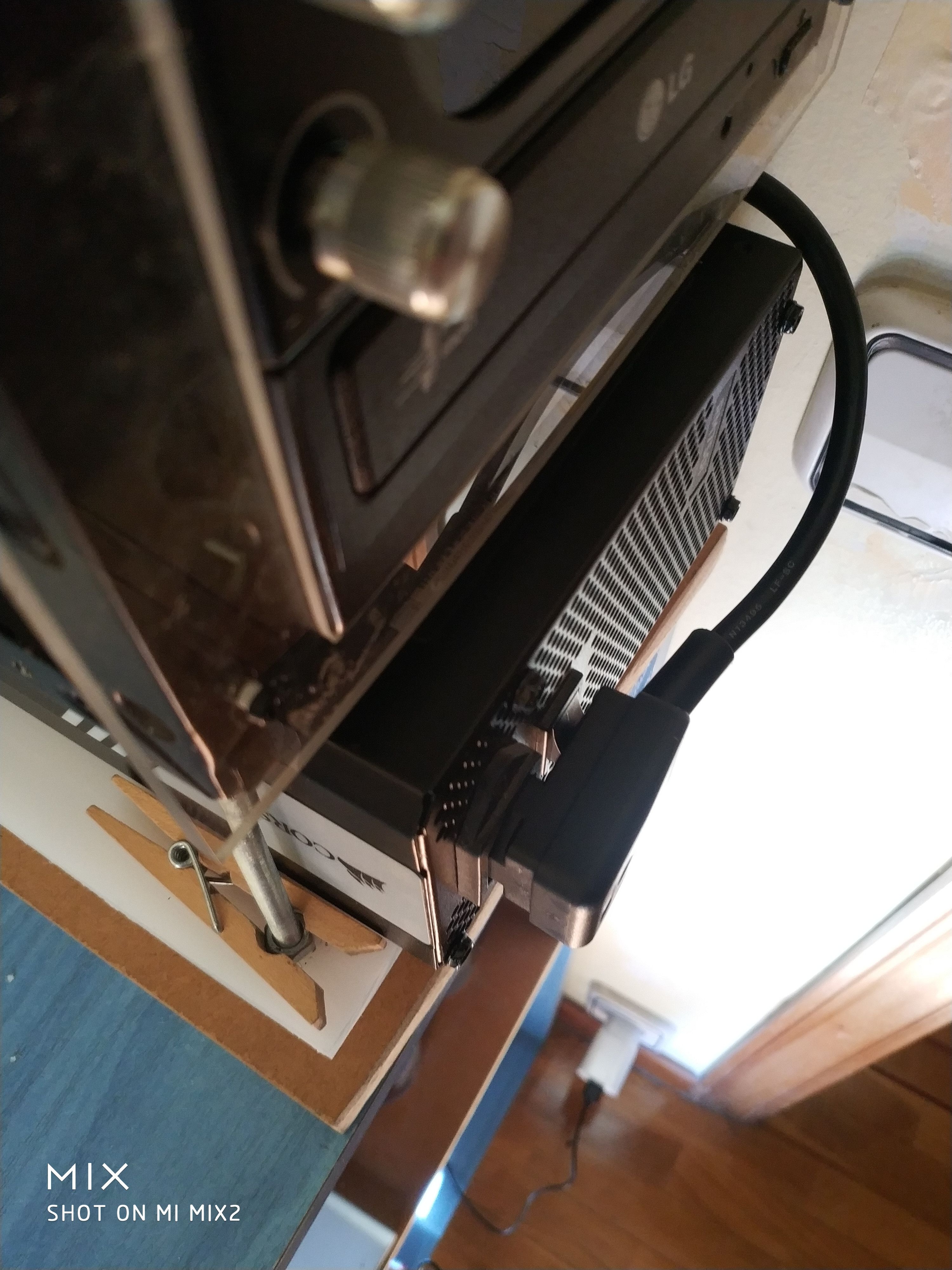
The only thing that strikes me a bit is the power supply cable at the front, but the overall is great.
Regarding the buttons for power and reset, I made a brutal button in my day with porexpan and a bottle cap, red death button style that has to be in every nuclear power plant control panel. In case you want to get ideas...
Best regards!
>> i7-2600K Sandy Bridge @4.4GHz || Noctua NH-D14 || ASRock Z77 Extreme4 || 4x8Gb G.Skill Ripjaws X DDR3 1600MHz || XFX RX 5700 XT 8Gb || SSD Samsung 850 PRO 256Gb & 850 EVO 500Gb || WD Caviar Green 1Tb || Barracuda 1Tb || Corsair TX650 V2 || M-Audio Fast Track Pro || KRK RP8 RoKit G3 || BenQ GW2750 27"
>> Athlon 64 X2 5600+ Brisbane @2.9GHz || Gigabyte GA-M61PME-S2 || 2x2Gb DDR2 Kingston 800MHz || Sapphire Radeon HD 5850 Xtreme 1Gb || Maxtor 320Gb SATA2 || OCZ ModXStream 500W Modular || TEAC PowerMax 120/2 || Acer X243w 24"
>> Intel Core2Duo E6600 Conroe @2.4GHz || Asus P5N32-SLI SE DELUXE || 2x1Gb DDR2 Kingston 800MHz || Asus nVidia GeForce 9800GT 1Gb GDDR3 || Seagate Barracuda IDE 80Gb 7200RPM || Linkworld LPK12-35 450W -
@Sylver
sorry but I don't intend to listen to you, a bottle cap?
original candidate
discreet is not "too " expensive. without colors or nonsense.

but....
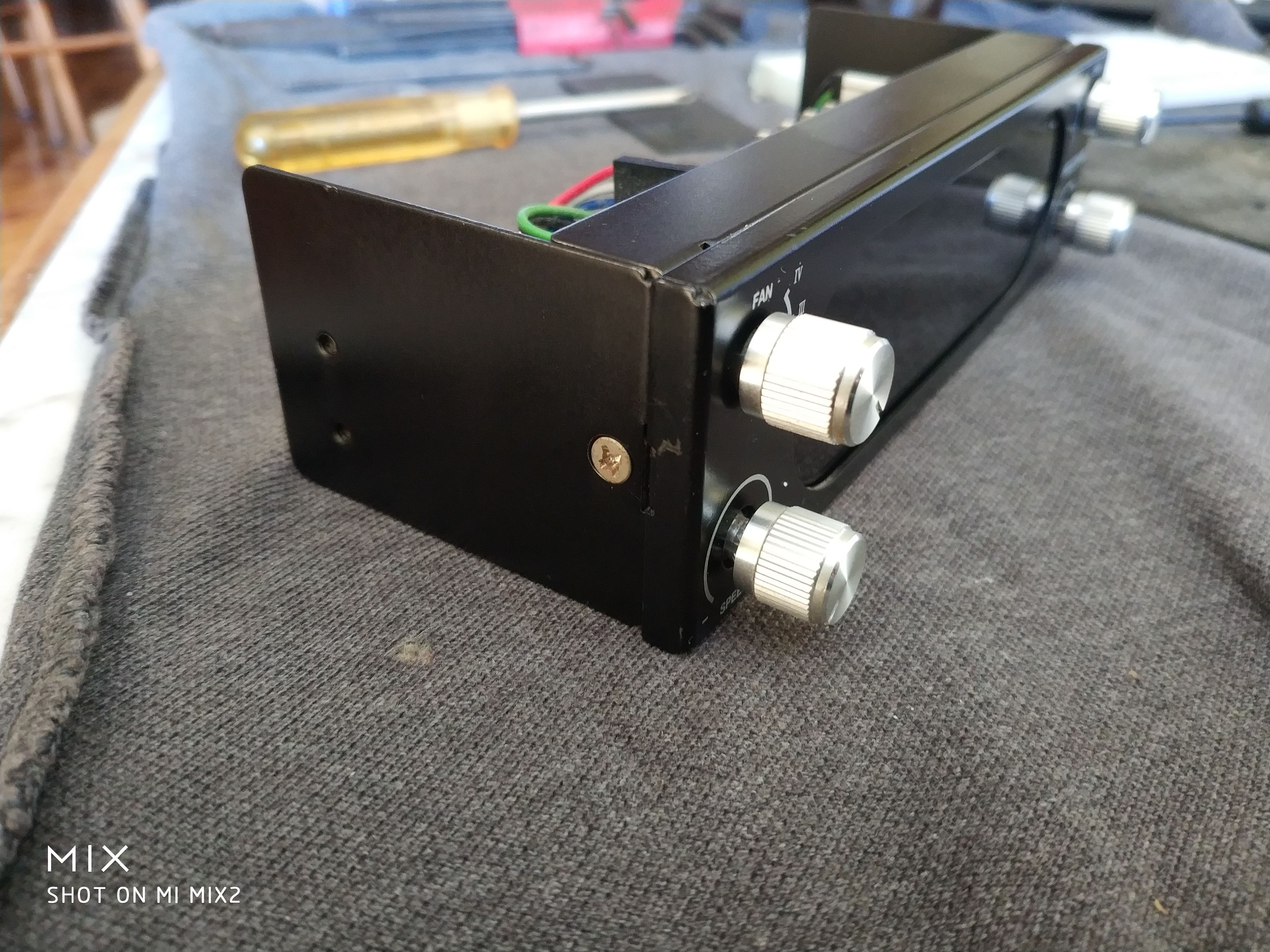
I've thought about it, I have 5.1 audio and the SCYTHE only has a jack to control the volume, I haven't even thought about installing it (the audio) all that trouble for what?
well, to eliminate the potentiometer (which is not soldered to the PCB, a bargain)
and put a three-position switch
already? I'll explain:
I have three positions: A on B nothing C reset
the control is always in B, I want to turn it on / off.. a "touch " to A and back to B
I don't know if I made myself clear.

but for that to work both the power and reset should have a "common" cable, which is not safe.
regardsabout the F.A issue...
I already commented that if I wanted a "chimney effect " I couldn't put the F.A behind, nor above or below, it had to go somewhere else
and it was in front. the cable... yes... I have another angled connector that covers the on off button but it's more discreet.regards 2
-
@Clipper I understand that you can't imagine it... I created a panel perfectly integrated into the top of the box where the button-plug was embedded. Visually, it was just a large red button with the letters ON, coupled above the switch, in turn all covered by a curved lid (I made the top of the box like a vault).
I understand that you want something more discreet, those push buttons you have put in look very good, seeing the work you do it won't cost you anything to integrate them into the design.
Best regards!
-
a photo will help
greetings.
more than the buttons, I like the idea of the switch. I'll have to do some testing before buying anything.
the next post...
custom cables
greetings -
@Clipper The thing is that I had photos of the process somewhere, but that was 8 years ago and so many hard drives...

I don't have the case physically at home, otherwise I would have taken some photos, although honestly it's not completely finished, I still had parts to paint and add the methacrylate (and put the components in of course). I went to study abroad for a few years and it was left standing and forgotten
Best regards!
Hello! It looks like you're interested in this conversation, but you don't have an account yet.
Getting fed up of having to scroll through the same posts each visit? When you register for an account, you'll always come back to exactly where you were before, and choose to be notified of new replies (either via email, or push notification). You'll also be able to save bookmarks and upvote posts to show your appreciation to other community members.
With your input, this post could be even better 💗
Registrarse Conectarse