Toshiba Satellite L750 - No video
-
When downloading the executable file *.exe

and run it.... I realize that this way is to update the BIOS working well the boot (Windows or CD-ROM)
In my case, then it would not work this way, I would have to get the BIN file, and then perform the process with the programmer....
Note: Where can I find the CH341A programmer and the clamp. And then how to do the whole process.
-
@Belzebu
I'll send you this link to Youtube that will explain it better than I can.
In the end, I've used it 4 or 5 times and less than once, with removable chips, not soldered. Every time I've used them, I've looked at the type it is (if it's from the CPU or GPU, they are different), I've looked for pin 1 (the one with the dot), I've connected the chip to the programmer and the programmer to the PC and with the software I've installed the BIOS.@Belzebu said in Toshiba Satellite L750 - Sin video:
When downloading the executable file *.exe
Well, that.exe is a self-extracting package. I suppose you can open it with winzip or winrar (I use linux and I've been able to see the contents of the package). Inside, there is an.iso file that inside has an.img file and already inside that.img is the BIOS binary.
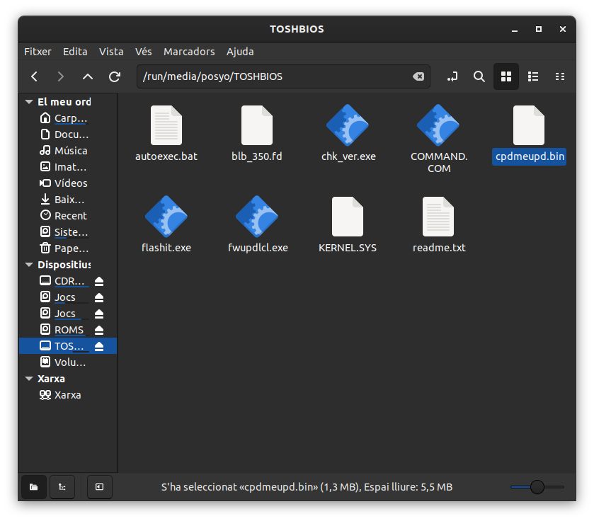
I don't know if that file will be compatible and can be dumped like that without more.@Belzebu said in Toshiba Satellite L750 - Sin video:
Note: Where can I find the CH341A programmer and the tweezers. And then how to do the whole process.
You'll find it on AliExpress or Amazon without any problem.
To be honest, I've come this far. I'm not an expert in this, just an amateur. If the information I've given you is useful, great. But I can't go any further...
-
@pos_yo
I am extremely grateful for your help and patience with me.
I have already ordered a programmer kit, so when it arrives I will try to figure out the process (I have nothing to lose anyway).
I just have these doubts left...
-According to the SPI FLASH scheme, the chip I think is the AMD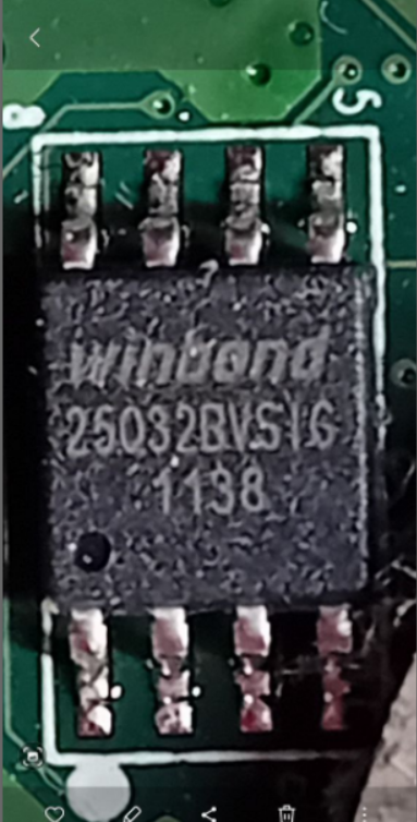
Does this difference affect anything in the whole process?
-Then, and as you rightly say... it is knowing if the BIN is correct.
-
@Belzebu The manufacturer has nothing to do with it because in the end the chip is nothing more than a nand, a memory. You just have to dump a BIOS compatible with the model of the motherboard and CPU and that's it.
-
Ok, understood the manufacturer's issue....
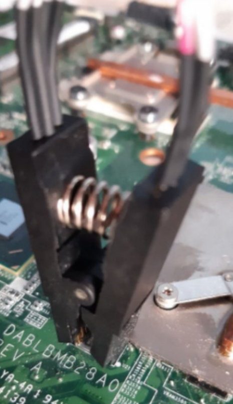
So the reference of the board model to find the compatible BIN would be the one printed on the image (DABLBMB28A0)?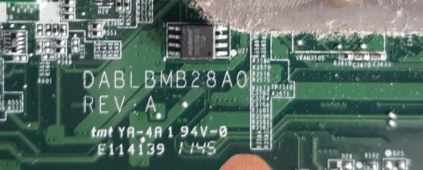
-
@Belzebu It would be a great reference...
-
Hello, I am returning to the topic after a while...since I had to get the CH341A programmer. The point is that once I have completed all the steps (Driver, Sof. Programmer) and connected the clamp to the BIOS chip (Winbond 25Q32BV) with the red cable connected to pin 1 or white point. The result is a detection error and it does not find the chip.
I put a capture of the message that appears.
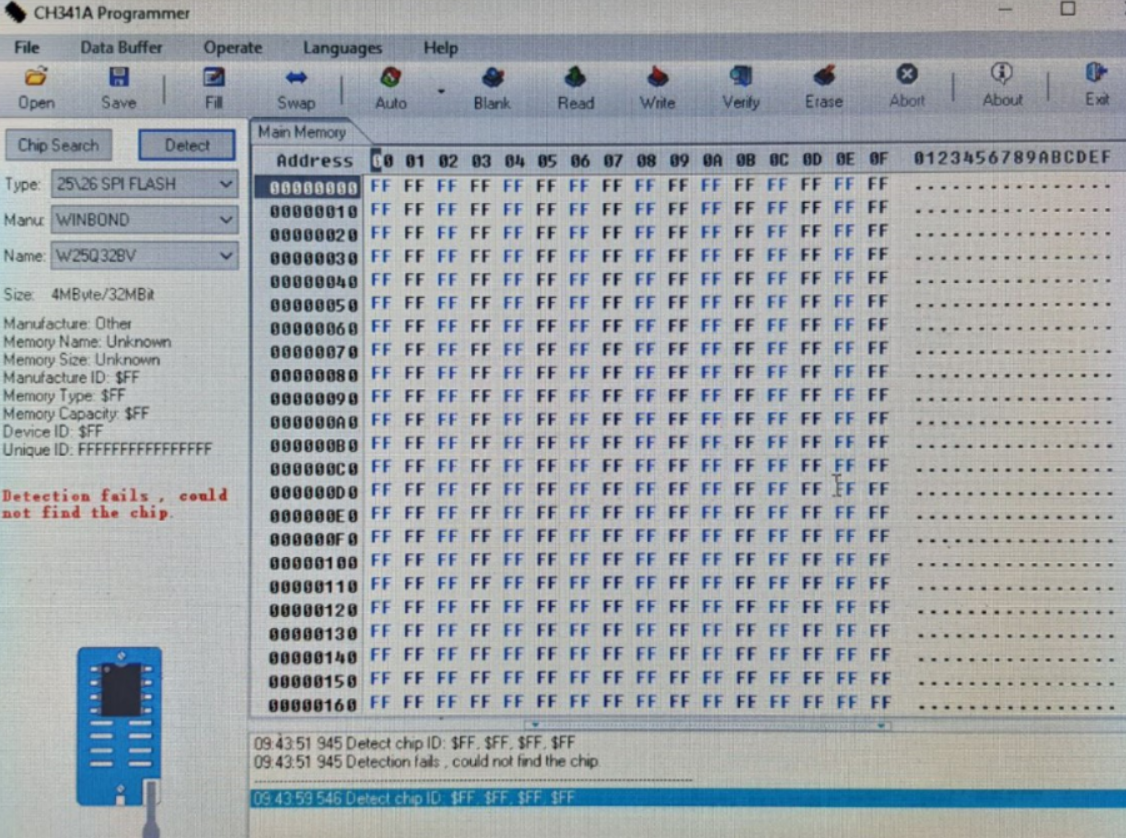
What can happen...this error may be related to the clamp being poorly connected, or maybe the chip is damaged?
-
@Belzebu said in Toshiba Satellite L750 - No video:
Hello, I'm revisiting the topic after some time...since I had to get the CH341A programmer. The point is that once I had completed all the steps (Driver, Sof. Programmer) and connected the clamp to the BIOS chip (Winbond 25Q32BV) with the red cable connected to pin 1 or the white point. The result is a detection error and the chip is not found.
I'll post a screenshot of the message that appears.
What could be happening...this error might be related to the clamp being poorly connected, or maybe the chip is damaged?
First, make sure you place the clamp on the Bios chip in the correct position. There is usually a reference on pin number 1, if you place the clamp incorrectly you could damage the chip...or that's what I think I've read.
Second, sometimes it's harder than it looks. Try to carefully check that the 8 pins are making contact with the 8 prongs of the clamp.
Third, but not least important, make sure you have the necessary drivers properly installed.
I used my BIOS programmer 3 years ago and this video helped me:
I hope it's useful for you, however if you don't look on YouTube you'll find a thousand tutorials, right now I'm very disconnected.In the event that your chip was really damaged, you just have to "look for" a similar one, desolder the old one and solder and then program it.
Best regards!!
-
Sorry, I can see that you basically did the drivers and other stuff, I mean, looking at the image again... I have the feeling that the clamp is connected to the chip incorrectly. It was hard for me to get the point, although I'm also a bit clumsy jajaja
Sorry that I come from work and my head is in another world!!
Greetings!!
-
Very grateful to both of you for your help... I can tell you that I think I did all the steps correctly... the only thing left for me to know is if this particular error could be due to the clamp being connected incorrectly to the chip's pins.
So I will perform more connection tests again.thanks and bye for now
-
In the end I had to disassemble the heatsink to be able to access the chip properly with the tweezers, so I think the pins match well.
Now the programmer is recognized, but I have another problem.... when I click "Detect", the program freezes (it won't let me do anything) and I have to disconnect the programmer for the system to work again.
Now I have another doubt that I don't know if it's the reason for the problem, and it is that in the programmer I don't know which is pin 1 (red or blue circle)
or maybe the ones on the top?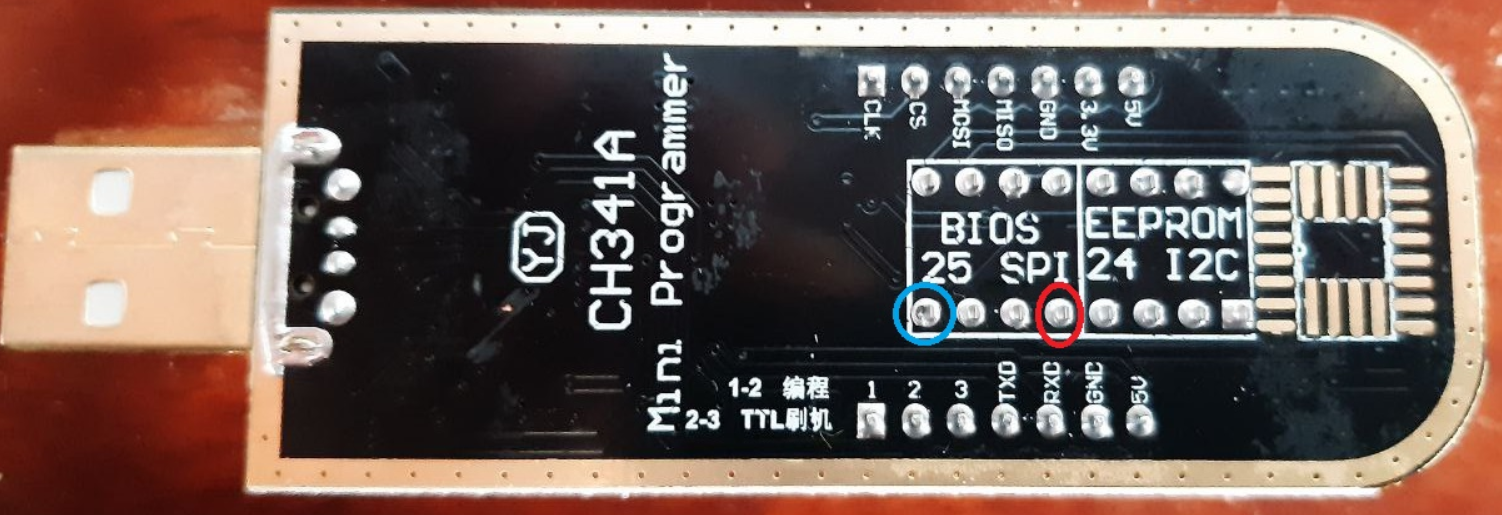
-
I'll send you a video to take a look at:
Although the video is generally interesting, just in case you check any more parts, I'll tell you several minutes of the video for you to look at:
30Min:38Seg.
06Min:18Seg.At least I see you have clear that you have to use the "25" scheme
")
If after this video you still have doubts, I suggest you take a look at Yotube to search for more tutorials about the CH341A programmer
There's not much more I can tell you, friend, it's time to investigate and take a risk. When I used it 3 years ago, that's how I managed to fix it, I already told you that it's quite difficult to get the 8 legs and the process will fail you a lot. And don't forget to have the programmer's drivers well set up, etc.Good luck!!
-
Hello,@_Neptunno_
I have already seen the complete video... and I see that it refers to the modification of the voltage from 5v to 3v, and from what I have read, the data pins work at 5v when the clamp connection goes directly to the chip on the motherboard.
I thought that this programmer regulated the voltage automatically,
So, I have to measure these pins to see what voltage they have, and if they have those 5v, then it's up to me to do the work of the video.Anyway, as you rightly say... I will keep looking and investigating.
thanks and salu2
-
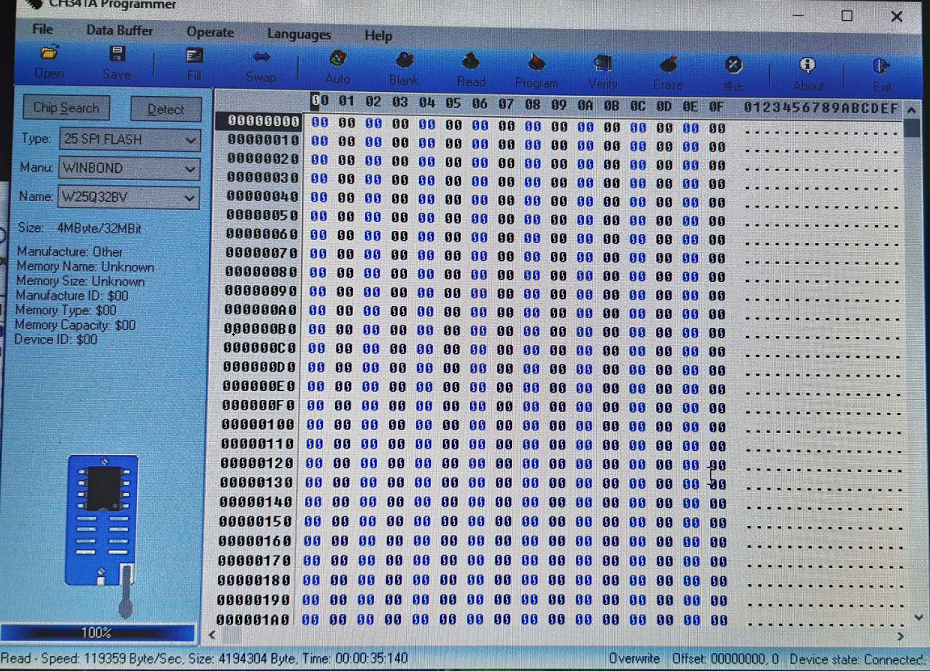
I have made the measurements with the tester... and indeed they give 4.9v on several pins.
On the other hand, I have tried to do the whole process with another different laptop and the results have been these:- In detect, on the left side the values are at 0.
- The reading process reaches 100%, although there is no data
then it no longer allows you to perform the following steps....
Here I have several doubts:
- The chip recognizes and works well with the 4.9v, and the problem is found in a bad connection of the clamp.
- The chip is blank or fried.
- How can you check the status of the chip (25Q32BV) in a simple way (Without oscilloscope)